All about I2C
Trill sensors use the I2C communication protocol to communicate with your hardware platform. I2C is a common communication protocol that’s supported by many popular maker platforms, including Bela.
This article provides an brief intro to I2C, and how it’s used in Trill.
Table of contents
An intro to I2C
I2C is a digital communication protocol that provides a convenient method of passing messages to, and getting data from, a network of sensors or devices.
I2C allows you to connect multiple devices (sometimes referred to as drones) to an I2C controller (known as the master). The master device can send messages to the drone devices, and the drone devices can send data back to the master device when asked.
One of the major advantages of I2C is that it only requires two wires for communication (data and clock), plus power and ground. The master and all the devices connect to these same two wires constitute a bus (see our getting started guide.)
The I2C protocol is 'voltage agnostic', meaning it doesn't have a specific supply voltage that it needs - the power voltage instead depends on the platform. All Bela systems operate I2C at 3.3V, as does Raspberry Pi, but Arduino I2C generally operates at 5V, and Teensy will operate at either 3.3V or 5V depending on the revision. In other words, you should always check the documentation of your board, if it's not included here, to verify what voltage you should use for the I2C device.
Pull-up resistors
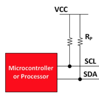
I2C is an open-drain/open-collector protocol. This means that any device operating on the bus will either drive the line low (when writing a 0) or not drive it at all (when not transmitting, or when writing a 1).
This protocol relies on the presence of pullup resistors that connect each of the SCL and SDA lines to Vcc, ensuring that the line goes back high when it is not actively driven low. Pullup resistors are usually have a value of a few kilo ohms, ideally between 2.2k to 4.7k. (If you’d like to read more about pullup resistors, lots of info can be found on this page).
Many common maker boards have on-board pullup resistors on their I2C lines (Bela has these, as well as Teensy 4 and later as well as Arduino Mega). Some maker boards don’t, or have weak pullups (higher value resistors have a weaker pullup effect). If pullup resistors on the I2C bus are missing or ineffective, devices connected to it might malfunction or not work at all, because they can’t establish or maintain consistent communication.
There are many variables that affect the I2C bus’s ability to return to a high voltage. These include the length of the device wires, the number of devices, material differences, and so on. As a result, there’s no one-size-fits-all approach - sometimes boards work fine with weak pullups but will suddenly cease to work if something changes.
We’ve noted the pullup status for several popular boards on the Get Started With Trill page, and we suggest getting to know the pullup configuration for the board you’re using. If your board has on-board pullups, start without external pullup resistors as it will likely behave as expected. If you experience problems (such as a Trill sensor not being detected or showing intermittent or inconsistent behaviour), try adding pullups yourself.
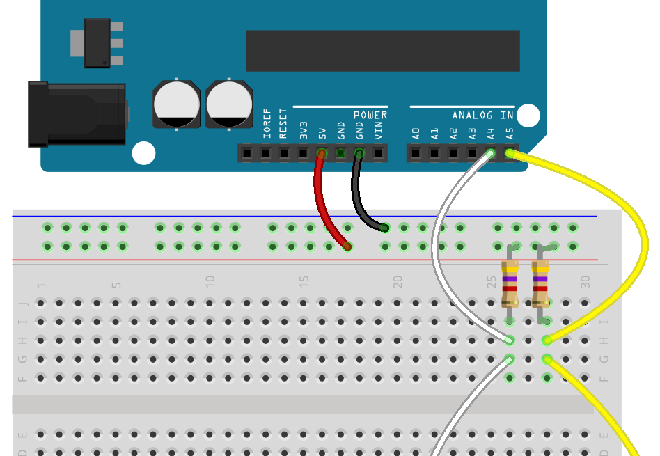
To add pullup resistors, add a 4.7k resistor between the pin and Vcc for both the SDA and SCL lines. You’ll need two resistors, one per line. Here’s an example of what this might look like if you’re using an Arduino (Arduino boards have on-board pullups but they can be disabled in software if you want to use external ones):
I2C addresses
Every I2C device must have a unique I2C address when connected to the same bus. The uniqueness of the I2C address is vitally important - if two or more devices on the bus have the same address, none of them will work properly.
Each type of Trill sensor comes with a unique default address (found in the first column of the table below). As well as the default address, each sensor type can have up to 8 additional addresses. This enables you to use up to 9 of the same Trill sensor type on a single I2C bus.
I2C addresses may be expressed in decimal or hexadecimal format, depending on the conventions and capabilities of the platform and programming language in use. For ease of use, we report the possible addresses for each Trill device type in both formats.
Here are the address numbers in hexadecimal:
| Trill Type | Default | Additional addresses |
|---|---|---|
| Bar | 0x20 | 0x21 0x22 0x23 0x24 0x25 0x26 0x27 0x28 |
| Square | 0x28 | 0x29 0x2A 0x2B 0x2C 0x2D 0x2E 0x2F 0x30 |
| Craft | 0x30 | 0x31 0x32 0x33 0x34 0x35 0x36 0x37 0x38 |
| Ring | 0x38 | 0x39 0x3A 0x3B 0x3C 0x3D 0x3E 0x3F 0x40 |
| Hex | 0x40 | 0x41 0x42 0x43 0x44 0x45 0x46 0x47 0x48 |
| Flex | 0x48 | 0x49 0x4A 0x4B 0x4C 0x4D 0x4E 0x4F 0x50 |
Here are the same addresses again, but in decimal format:
| Type: | Default address | Available addresses |
|---|---|---|
| Bar | 32 | 33 34 35 36 37 38 39 40 |
| Square | 40 | 41 42 43 44 45 46 47 48 |
| Craft | 48 | 49 50 51 52 53 54 55 56 |
| Ring | 56 | 57 58 59 60 61 62 63 64 |
| Hex | 64 | 65 66 67 68 69 70 71 72 |
| Flex | 72 | 73 74 75 76 77 78 79 80 |
Changing your Trill sensor’s address
If you want to use more than 1 of any single sensor type, you’ll have to change the I2C address of each additional sensor so they can be differentiated on the I2C bus.
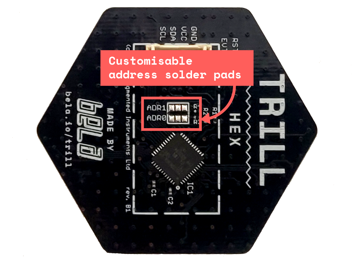
Normally this would involve changing firmware code, and then re-flashing the firmware on the device - a complicated process. To make addresses easier to customise, each Trill sensor has six solder pads on the back. By connecting these with a blob of solder in a specific way, you’ll be able to change your sensor’s address.
The address pads are found here:
How custom addressing works
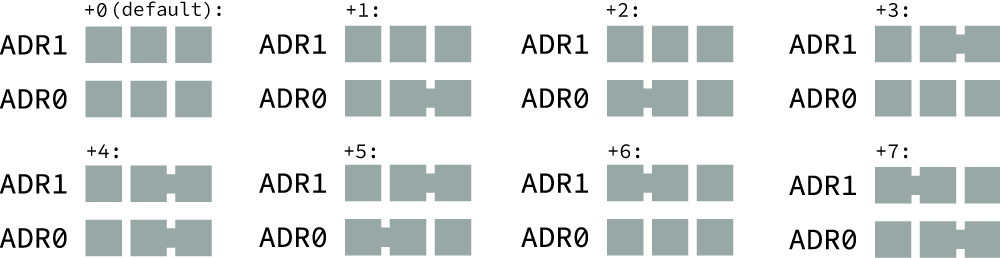
The two rows of three pads represent two tri-state numbers. This means each row of 3 can represent the numbers 0, 1 or 2. 2 sets of tri-state values can represent 9 (3^2) values - or the numbers 0-8.
These are the values of each pair of pads:

By connecting up to one pair of pads on each row, we can create unique addresses for 7 more sensors in addition to the default one. Here’s the configuration for each value from 1-7 that can be added to the default sensor address:
You might notice that you can also add an 8th sensor. This is possible, but if you add 8 to the default address, you will give the sensor the default address of the next sensor type. For example: if you're using 9 Trill Bar sensors, they will have addresses 32, 33, 34, 35, 36, 37, 38, 39, and 40, but 40 is the default address for Trill Square. Therefore, if you are also using a Trill Square sensor you will have to connect some solder pads on it to give it a new, unique address.
How to connect the pads
Connect pairs of solder pads using a solder bridge. A solder bridge is when two points on a circuit board are connected by solder.
Start with a hot soldering iron. Heat up the middle pad, and carefully melt a little blob of solder onto it.
Then, heat up the pad that you want to connect to the middle one - either to the left or the right. Melt a little blob of solder onto it.
Finally, heat up the two blobs. Often when they’re liquid they’ll connect on their own due to the solder’s surface tension and their close proximity. If they don’t, try to draw them together with a hot iron, or add a little more solder to one side and try again. Be very careful not to connect any other solder pads!
To disconnect a solder bridge, heat it up briefly with a hot iron, and remove the hot solder using a solder sucker or solder wick.
On each row, only ONE side can be connected to the middle pad! If both sides are connected to the middle pad, you will connect the system VCC and GND. This means that the board connected to the Trill sensor will not power up with the sensor connected, and the board and/or the sensor could be damaged if you attempt to power them up while Vcc is connected to GND. We therefore recommend that, after soldering and before connecting your sensor, you verify with a multimeter that the row is only connected on one side, and that there is no continuity between Vcc and GND. If you find that you've accidentally connected the middle pad to both sides, don't despair - this can be undone by removing the solder with a solder sucker or wick.