Programming Trill with Arduino
Once you have your Trill sensors hooked up, you’re ready to start writing code to make them come to life.
This article explains how to get started with the Arduino micro-controller and Trill and walks through some of the default examples that come with the Arduino library.
Table of contents
Working with Arduino
Installing the Trill library
Download the Arduino Trill library from the Trill-Arduino Github repo.
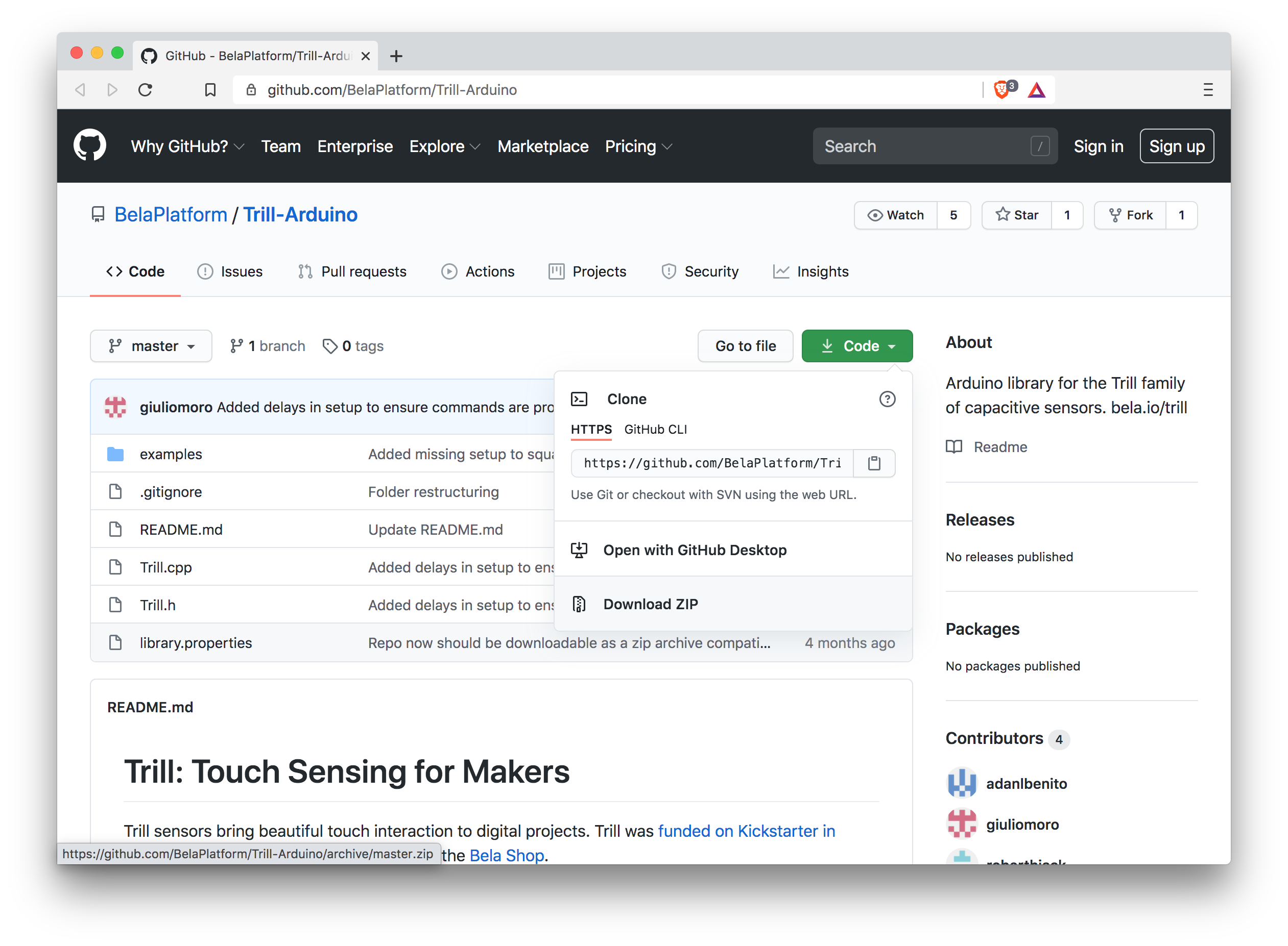
To install the Trill library using the Arduino IDE, download it by clicking on Clone or download -> Download ZIP and then follow the instructions provided by Arduino.
Connecting the hardware
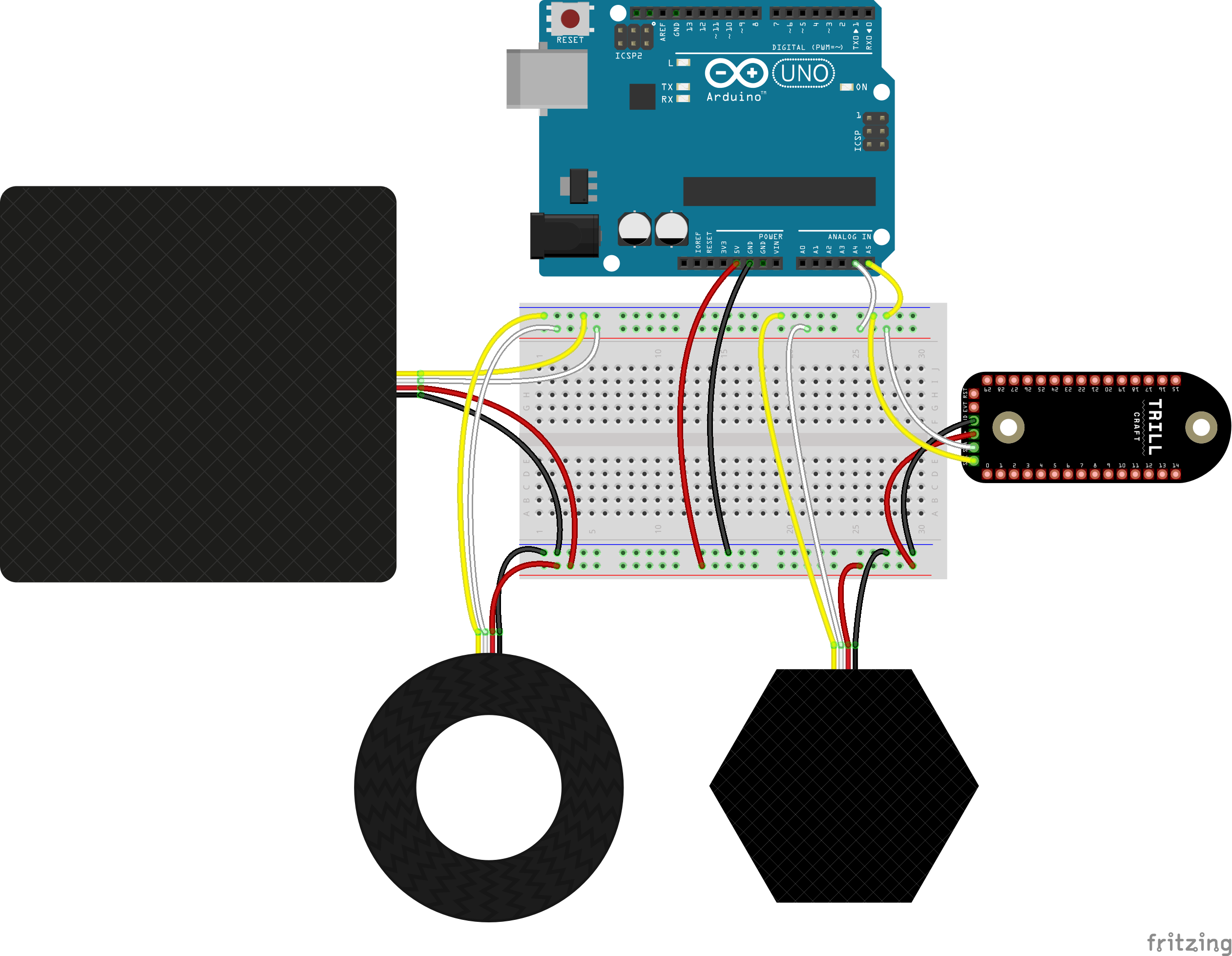
Connect your Trill’s SCL, SDA and GND to the appropriate pins on your board, and connect VCC to 5V. This is what the setup looks like if you’re using an Arduino Uno:
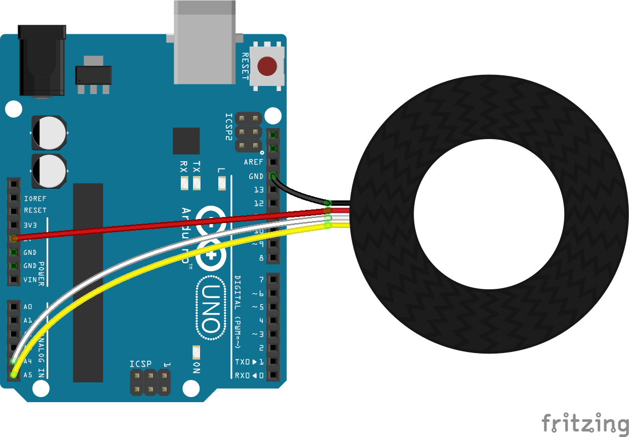
For other Arduino boards have a look at our guide for connecting different Arduino boards. If you’re using a Teensy board then check out our guide for connecting Trill sensors to Teensy.
Arduino example sketches
To begin with let’s run one of the [...]-print examples. When the Trill library is installed you’ll have access to the included examples. Within the Arduino IDE go to File > Examples > Examples from Custom Libraries > Trill and find the example named after your Trill sensor followed by -print (such as bar-print or craft-print). Upload the sketch to your board.
Here is the code from a sketch that works with Trill Bar:
#include <Trill.h>

Trill trillSensor;
boolean touchActive = false;

void setup() {
  // Initialise serial and touch sensor
  Serial.begin(115200);
  int ret = trillSensor.setup(Trill::TRILL_BAR);
  if(ret != 0) {
    Serial.println("failed to initialise trillSensor");
    Serial.print("Error code: ");
    Serial.println(ret);
  }
}

void loop() {
  // Read 20 times per second
  delay(50);
  trillSensor.read();

  if(trillSensor.getNumTouches() > 0) {
    for(int i = 0; i < trillSensor.getNumTouches(); i++) {
        Serial.print(trillSensor.touchLocation(i));
        Serial.print(" ");
        Serial.print(trillSensor.touchSize(i));
        Serial.print(" ");
    }
    Serial.println("");
    touchActive = true;
  }
  else if(touchActive) {
    // Print a single line when touch goes off
    Serial.println("0 0");
    touchActive = false;
  }
}
Let’s walk through the sketch to see what’s happening here. On the first line we include the library file that we need, Trill.h, which gives us all the necessary functions for working with the Trill sensors.
Then we create a Trill object. You can give it any name you like, in this example we call it trillSensor and we will use that name throughout this sketch to refer to that particular sensor.
Initialising the sensor
All of our initialisation of the sensors happens in the setup() function which will be familiar to you from other Arduino projects. The important line within setup() is the following function which sets up our Trill sensor:
int ret = trillSensor.setup(Trill::TRILL_BAR);
if(ret != 0) {
  Serial.println("failed to initialise trillSensor");
  Serial.print("Error code: ");
  Serial.println(ret);
}
trillSensor.setup() requires just one argument which is the sensor name.
Specify the type of Trill sensor you’re using. The options are Trill::TRILL_BAR, Trill::TRILL_SQUARE, Trill::TRILL_CRAFT, Trill::TRILL_HEX or Trill::TRILL_RING.
This initiates the sensor. If this initiation is successful, the function will return a 0. Therefore we check its return value and if any other value is received, we print an error message and don’t start because the sensor can’t be found.
Custom address
The second optional argument to setup() will define the address of the sensor. This is useful for cases in which you have changed the default address of a sensor via the solder bridge because you are using multiple sensors of the same type at once. If not provided, the default address for the specified device type will be used instead.
Reading from the sensor
Reading from the sensor all happens in the loop() function. At the top of loop() we call trillSensor.read(); which pulls the raw readings from the sensor. Notice that at the top of this function we have a delay of 50 milliseconds which means we are reading from the sensor 20 times per second. This is a good amount of delay for a stable reading from the sensor.
Position and touch size
This is the part of loop() which deals with reading the position and size of a touch:
if(trillSensor.getNumTouches() > 0) {
    for(int i = 0; i < trillSensor.getNumTouches(); i++) {
        Serial.print(trillSensor.touchLocation(i));
        Serial.print(" ");
        Serial.print(trillSensor.touchSize(i));
        Serial.print(" ");
    }
    Serial.println("");
    touchActive = true;
  }
This if statement first checks whether there is a touch present on the sensor with trillSensor.getNumTouches() which returns the number of active touches. We next have a for loop which will cycle through the number of active touches. Within this for loop, for every active touch, we then have two methods for reading from the sensor: trillSensor.touchLocation(i) which gives the touch position on the sensor and trillSensor.touchSize(i) which gives the touch size.
If you run this example you’ll see that for every touch on the sensor a new pair of readings are printed to the serial monitor, as can be seen above. Each pair of values consists of the position on the sensor followed by the touch size. The position value returned will be an int which depends on the number of pads along each axis of the sensor according to the following equation: 128 * (numPads -1) (see below table).
| Trill Sensor | Number of pads per axis | Position value range | Approx size value range | Number of axes |
|---|---|---|---|---|
| Bar | 26 | 0-3200 | 0-4566 | 1 |
| Ring | 28 | 0-3456 | 0-5000 | 1 |
| Square | 15 | 0-1792 | 0-3780 | 2 |
| Hex | 15 | 0-1920 | 0-4000 | 2 |
| Flex | 30 | 0-3712 | 0-1200 | 1 |
If you would like a deeper explanation of why each of the sensors has a different range then check our technical note on how touch size is calculated.
Looking at the Raw readings
In the above sketch we have been looking at the ‘cooked’ sensor values where touch position and size are pre-calculated for you on the chip of the Trill Sensor. This mode is know as CENTROID mode and is the default mode for Trill Bar, Square, Hex and Ring. This mode processes the readings of the individual capacitive sensing channels taking into account the geometry of the circuit board, in order to compute the position and size of several discrete touch points.
Another way of receiving the readings from the Trill sensors is to look at the raw capacitance of each individual pad. To do so we need to set the Trill sensor into DIFF mode. We can change the mode of a sensor in setup() by calling trillSensor.setMode(). There are four mode options CENTROID, DIFF, RAW and BASELINE. For a full discussion of the different modes and what they mean see our guide.
A good sketch to run to see the raw readings is raw-multi-print which, once uploaded to the board, will print the raw values of any sensor connected to the Arduino to the serial monitor. If you do so you will see something like below where every individual pad on the sensor has a reading:
Setting the Trill sensors in DIFF mode is particularly useful for working with Trill Craft and this is in fact the default mode of this sensor.
Visualising touches
To accompany the Arduino sketches we have also created a Processing library and examples which can be used to visualise the touches on the sensor. Processing is an open source software environment for creative coding with a focus on visual output. You will need to download the latest version of Processing to run these visualisations.

Step 1: Install the Trill Processing Library
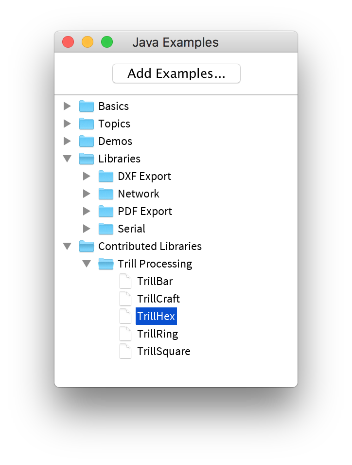
The latest version of the Trill Processing Library can be downloaded here. To install this library please follow this guide on how to install a contributed library. Make sure to restart Processing after completing this process. If the library is properly installed you will be able to find the Trill examples by navigating to File > Examples... > Contributed Libraries.
Step 2: Run the Arduino sketch
Make sure that the [...]-print sketch appropriate to your sensor is running on your Arduino before running the Processing sketch. Data will be sent from the Arduino via serial to the Processing sketch to be visualised showing the location and size of multiple touches.
Step 3: Run the Processing sketch
Run the Processing sketch appropriate to your sensor type to launch the programme and see the touches visualised in realtime. If you have any issues make sure you are running the sketch with the right name or your sensor (e.g. TrillRing if you’ve got a Ring connected) and try stopping the Processing sketch before running the Arduino sketch again.
Utility sketches
Detecting all connected sensors
If you have many different sensors connected to your Arduino with different addresses, then the detect-all-devices sketch can help you verify that the devices are all connected and detected properly and visualise their I2C addresses.
This example is a handy utility which will identify all connected I2C devices and print information on them to the console. When the program runs it will print the address and sensor type of all the Trill sensors you currently have connected to the I2C bus on the serial port.
This is particularly useful if you are unsure of the address of the sensor after changing it via the solder bridges on the back. This example will also give you a total count of the amount of Trill sensors connected to your Arduino.
Print sensor information
The print-details example will print to the serial monitor information on the currently connected sensor. For example:
Trill Device Details:
	- I2C address: #20 (32)
	- Trill device type: bar
	- Firmware version: 2
	- Sensor mode: centroid
	- Number of available centroid dimensions: 1
	- Number of capacitive channels: 26
	- Number of button channels: 0
Make sure you specify the correct sensor type in the call to trill.setup() before running this example.
Adjusting settings
When working with Trill Craft in particular you may want to adjust the sensitivity and noise threshold settings. In the craft-settings example you can adjust these settings by typing commands into the Arduino Serial Monitor by writing one-line commands followed by a semicolon and the value to be set:
	prescaler: prescalerValue
	threshold: thresholdValue
	bits: numberOfBits
For a full discussion of the different sensor settings and how to use them best with Trill Craft see our guide to the different sensor settings.
After experimenting with different settings using this example you can then make sure you use the correct settings for your sensor arrangement by using the trillSensor.setPrescaler() and trillSensor.setNoiseThreshold() functions in setup().
Visualising different settings
There is also a handy Processing counterpart for this example called TrillCraftSettings which you will find as part of Processing library as discussed above. When you run this processing sketch alongside the craft-settings Arduino example you will see a bar graph with the raw readings from each of the 30 channels of Trill Craft.
in order to use this Processing sketch you will need to install the `controlP5` library which you can do in Processing via `Sketch > Import Library... > Add Library...`.
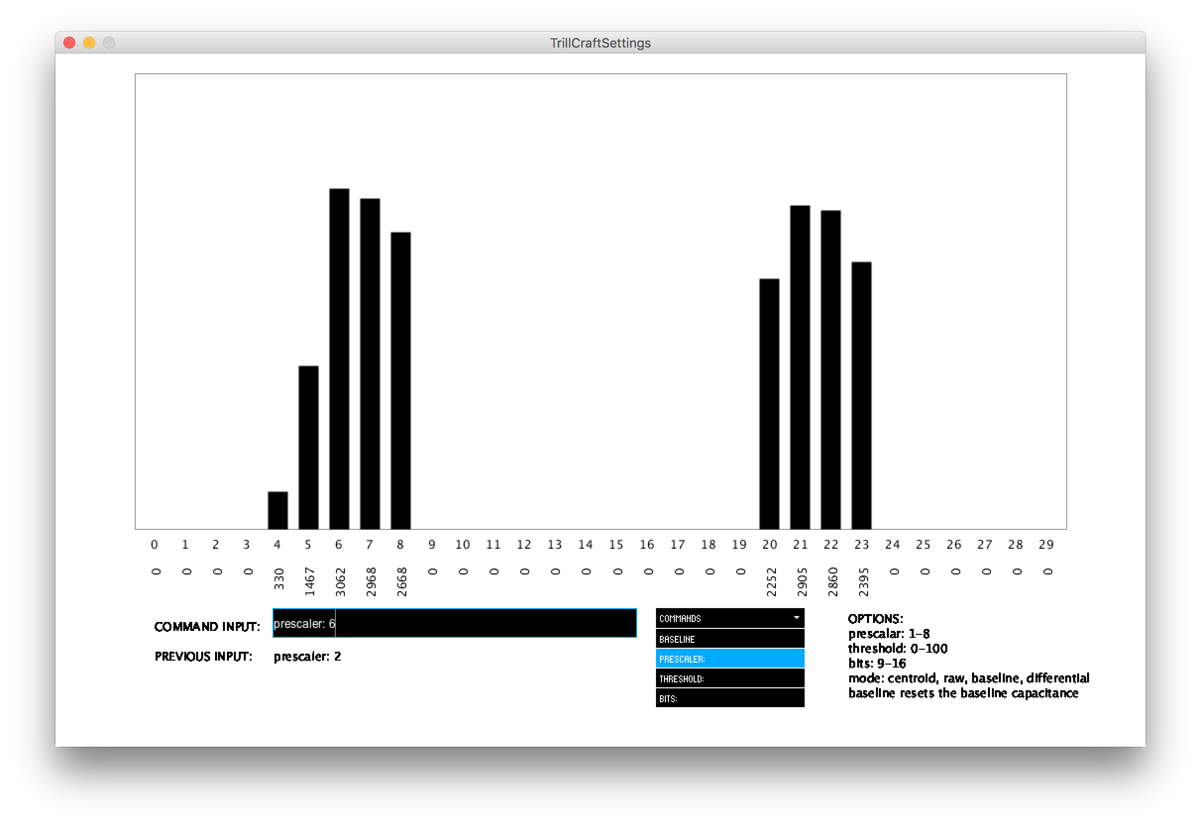
You can interactively change the settings and see the effect on the readings. Select the setting you would like to change from the dropdown menu which will auto-populate the console window, add the value that your would like to change in the console (check the comment in the example for the expected values for each setting), and hit enter to apply that setting. You will now see effect of that setting on the readings in the bar graph.
Technical note on how touch size is calculated
In the above table you can see the ranges for touch size also vary per sensor. The touch size is the sum of the activation across all pads that make up a touch. Each pad has a maximum activation value of (2numBits - 1), so 4095 at 12 bits (default), but you would only achieve this in DIFF (differential) mode if the base capacitance was zero and the activation was saturating the sensor’s reading, which is not very likely.
The usable range of differential activation with 12 bit resolution is more likely to be around 1000 or 2000 and also depends on the prescaler settings. The full range would only ever be used in situations where you had a huge finger that touches all the pads at once and is connected to a huge body which saturates all the pads which otherwise have 0 activation, then you would get a touch size value of ((2numBits - 1) * numPads), i.e. 4095 * 30 = 122850.
In reality and with regular sized fingers connected to regular size bodies you can expect that a touch would comprise 3 or 4 pads and an activation value around 1000 or 2000, so between 3000 and 8000 as a reasonable maximum touch size at 12 bit, depending on surface, geometry, wiring, prescaler settings and how you place your finger on the sensing surface. Note that in the Bela library we have more computing power at our disposal and so we normalise these readings to 0-1. In the case of the Arduino microcontroller this would eat up a lot of available computing power.