Get started with Trill
Trill sensors were designed by the team that brought you Bela, but they’re compatible with any microcontroller that supports the I2C communication protocol, including Arduino and Raspberry Pi. You can download libraries and examples for Linux platforms (Raspberry Pi, Beaglebone, etc…) from this repo, and libraries for Arduino-compatible boards (including Teensy) from this repo.
This article explains how to get started with Bela, as well as other popular maker platforms. We’ll assume that you have some jumper wires and a breadboard available to connect things up quickly.
Table of contents
Get your Trill sensor ready
If you’d like to read all the technical details in one place, download the Trill data sheet.
Trill Bar, Square, Hex, Ring
Trill Bar, Square, Hex and Ring each come with a QWIIC cable that breaks out the sensor pins to wires. Insert the QWIIC connector to the port on the back of your Trill sensor, making sure it’s in tight. You can use the loose wires to connect your Trill sensor to your maker board by plugging it in directly, or connecting via a breadboard.
See the section for your maker platform for details and diagrams.
Trill Craft
Trill Craft comes with a 6-way, 90 degree pin header. Solder this to the 6 pins at the bottom of the Craft sensor so you can insert it into a breadboard and connect it to your system using jumper wires.
Trill Craft’s 30 sensing channels are broken out to pads, 15 along each side of the sensor. These are left open so you have the freedom to connect to your custom interface in the way that suits you best, whether that’s soldering it to wires, sewing it with conductive thread, or adding header pins.
If you want to connect Trill Craft to a breadboard for prototyping, solder a 15-way straight pin headers to each side, and insert it into a breadboard.
Trill Flex
There are two parts to Trill Flex: the base (where you’ll find the Trill chip and a high-density connector) and the flexible sensor (made from flex PCB).
Trill Flex also uses a QWIIC cable that breaks out the sensor pins to wires. Insert the QWIIC connector to the port on the back of your Trill Flex base, making sure it’s in tight. You can use the loose wires to connect your Trill sensor to your maker board by plugging it in directly, or connecting via a breadboard.
Then connect the flexible sensor to the base. On the end of the base there’s a clip connector. Push the clip up to open it. Insert the end of your flex sensor in the clip, press down firmly, and that’s it - your sensor is ready to go! See working with Trill Flex for more details.
Identifying connectors
If you’re using a Trill sensor with one the provided QWIIC cables, wire colours are:
| Signal | Wire color |
|---|---|
| Vcc | Red |
| GND | Black |
| SCL | QWIIC: Blue, Grove: Yellow |
| SDA | White |
If you’re using Trill Craft, you’ll use the pins on the bottom (short flat end) of the sensor. These pins are labelled.
If you are using a different cable from the one that shipped with the sensor, always double check the signal a given wire is attached to by using the labels next to the QWIIC connector on the back of the sensor.
Bela & Bela Mini
1. Connect Trill to your Bela system’s I2C pins
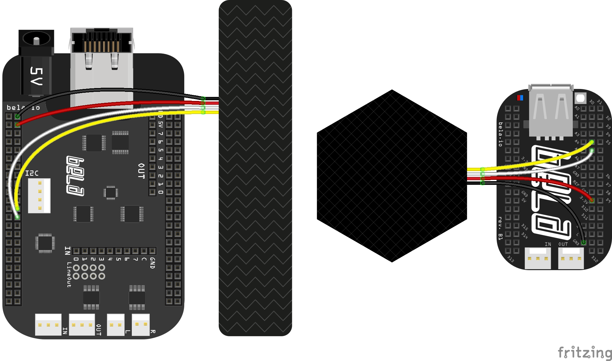
Both Bela and Bela Mini support I2C communication, and require a 3.3V supply. Locate the SDA, SCL, GND and 3.3V pins using the interactive diagram in the Pin Diagram tab in the Bela IDE, or use our online pin diagram.
Connect Trill’s SCL, SDA and GND pins to these pins on your Bela system, and connect Trill’s VCC to 3.3V. Here’s what the setup looks like for Bela and Bela Mini:
2. Open an example in the IDE
The Bela IDE ships with several Trill examples in the Examples tab. Locate the Trill section, and select the right example for your sensor.
Sensor-specific examples
Each sensor type has one example that makes sound and another that has a GUI for visualising touches, so you’ll be able to see your Trill in action right away.
- Trill Bar: Use
bar-visualto display touches in realtime,bar-ledto use touch position to control a set of LEDs, orbar-soundfor a multitouch theremin. - Trill Square: Use
square-visualorsquare-soundto get started with x-y control orsquare-multitouchfor an example of pseudo-multitouch. - Trill Craft: Use
craft-visualorcraft-soundfor a touch controlled oscillator bank that can be activated by any conductive material. - Trill Hex: Use
hex-visualorhex-soundfor examples of synth control. - Trill Ring: Use
ring-visualto visualise touch orring-soundfor an interactive Shepard-Risset tone that infintely ascends or descends. - Trill Flex: Use
general-visualto visualise touches orcustom-sliderto create sliders from custom ranges of pads.
Build and run the example using the Run button. If this is the first Bela project you’ve ever run, it will take a few minutes to build all the dependencies it needs). Each sensor type also has a Pure Data project showing you how to get started in PD if that’s your language of choice.
General examples
We have also included a series of examples that are designed to work across all sensor types. general-print will print the raw values of the sensor channels to the console of the IDE, whereas general-visual gives you a graph display of the individual sensor channels.
If you would like to experiment with different sensor settings and to understand their effects then run general-settings and launch the GUI where we have designed a full dashboard that allows you to change settings in realtime and see the resultant sensor readings. If using multiple sensors of the same type together then have a look at general-custom-address which will explain how update the address away from the default.
Trill utilities
We have two other utility examples which are useful tools for working with Trill and Bela. detect-all-devices will print information on all connected Trill sensors to the console of the IDE. This is very handy for situations in which you have changed the address of a sensor and can’t remember its exact value. The multiple-devices example scans the I2C bus for any connected Trill sensors and will then generate an interactive GUI element for each one. This is great for quickly visualising multiple sensors.
3. Launch the GUI visualiser, and try it out!
If you are running one of the -visual project then click the GUI visualiser button in the toolbar. The visualiser will open in a new tab.
While your project is running, you’ll be able to see your Trill sensor responding in real time.

Some Bela notes
-
If you are using Bela software older than May 30 2020, you will have to update your Bela software to get the latest Trill library and examples.
-
In older versions of the Bela software (before v0.3.7b) the I2C-1 bus speed is limited to 100kHz, while newer versions use 400kHz. Update your Bela software to address this.
-
Trill sensors use the Trill library. If you want to start a Bela project from scratch that uses Trill, create a new project and include the Trill library from the Libraries tab by copying the include statement and pasting it at the top of your
render.cppfile.
Arduino
1. Connect Trill to your Arduino’s I2C bus
Arduino Uno, Ethernet, Mega2560, Leonardo and Due all provide an I2C bus, but the pins for I2C differ depending on the board:
| Arduino Model | SDA (data) pin | SCL (clock) pin |
|---|---|---|
| Uno, Ethernet | A4 | A5 |
| Mega2560 | 20 | 21 |
| Leonardo | 2 | 3 |
| Due** | 20 | 21 |
| Micro | 2 | 3 |
** - Arduino Due has 2 I2C buses. Our library uses pins 20 and 21.
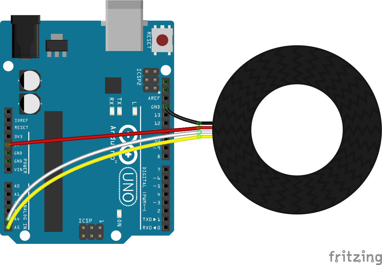
Connect your Trill’s SCL, SDA and GND to the appropriate pins on your board, and connect VCC to 5V. This is what the setup looks like if you’re using an Arduino Uno:
2. Download and install the Arduino Trill library
Download the Arduino Trill library from the Trill-Arduino Github repo.
To install the Trill library using the Arduino IDE, download it by clicking on “Clone or download -> Download ZIP” and then follow the instructions provided by Arduino.
3. Open and run the -print example for your Trill sensor
When the Trill library is installed you’ll have access to the included examples. Go to File > Examples > Trill and find the example named after your Trill sensor followed by -print (such as bar-print or craft-print). Upload the sketch to your board.
When it’s uploaded, open the Arduino serial monitor and touch your Trill sensor. This sketch prints the values from the Trill sensor to the serial monitor. You should see lots of numbers!
Some Arduino notes
-
Arduino’s I2C communication operates at 5V, so your Trill’s VCC pin should connect to a 5V supply.
-
Arduino Mega has on-board pullup resistors on the SDA and SCL pins, but other Arduino models do not. We found that when using one Trill sensor with the Arduino Uno pullups were not required, but your results may vary (especially when using multiple sensors), so if you experience problems try adding 4.7k resistors to the SDA and SCL lines. If you want to use external pullup resistors with the Mega you can disable the internal ones in software. Find details on I2C communication on various Arduino boards in the
Wirelibrary documentation.
Raspberry Pi
We have tested Trill with a Raspberry Pi running the latest build of Raspbian available on May 25 2020. Raspbian is a full version of Linux that is the Raspberry Pi Foundation’s official operating system.
1. Connect Trill to your Raspberry Pi’s I2C pins
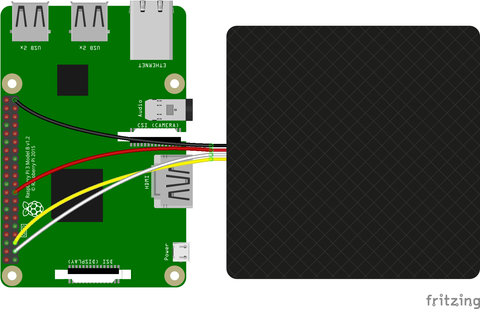
Connect your Trill’s SCL, SDA and GND to the appropriate pins on your board, and connect VCC to 3.3V. This is what the setup looks like if you’re using a Raspberry Pi 3:
2. Enable I2C on your Raspberry Pi
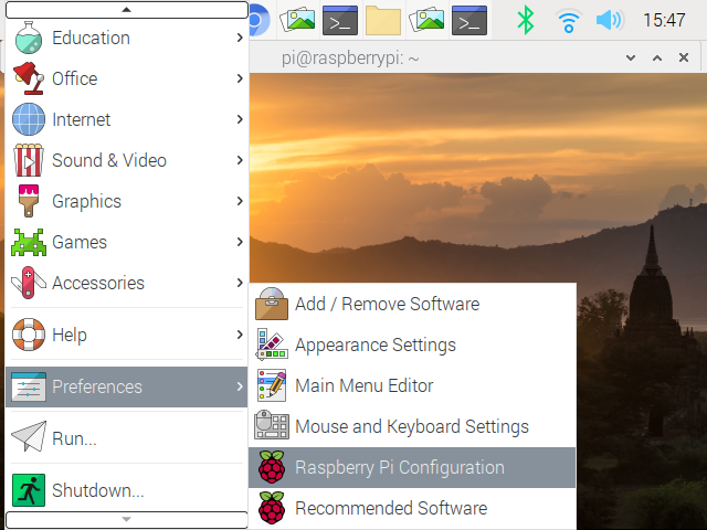
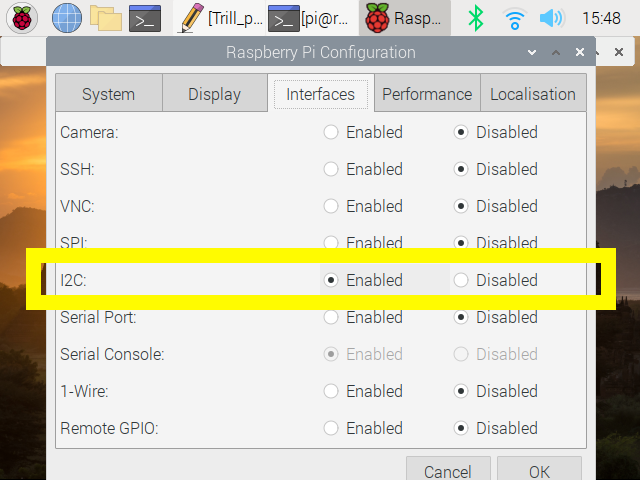
When you have your Trill sensor hooked up, confirm that I2C communication is enabled on your Raspberry Pi (it is disabled by default). Go to Preferences > Raspberry Pi Configuration in the system menu:
In the next dialog box, click the Interfaces tab at the top, and make sure the I2C option is set to Enabled:
3. Test your Trill setup
To make sure that your Trill sensor is hooked up properly and working, we’ll use i2cdetect, a command line tool that comes with Raspbian. In a terminal, type the following:
$ i2cdetect -y -r 1
The -y flag disables I2C’s interactivity for testing; the -r flag is used to detect I2C devices; and 1 is the number of the I2C bus with the pins used in the diagram above.
If your Trill sensor is working properly, it will be recognised. Here’s the output when we ran i2cdetect on a bus with an experimental Trill sensor that had the address 18:
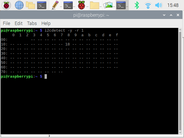
If your Trill sensor is recognised, your I2C settings are configured and working properly!
4. Download the Trill resources for Linux
Raspberry Pi uses the Trill library and examples for Linux.
Clone or download the Trill resources from the Trill Github repo. The examples in Trill/examples/ are C++ projects that will run on Raspberry Pi and other Linux computers. These use the libraries in Trill/lib/.
5. Build the library files and run an example
On the command line, navigate to the folder Trill/examples/. In this folder, build the libraries and compile the included examples by running the make command:
$ make
To run the general-print example, navigate to the general-print/ folder and run the compiled example. You have to pass two arguments: the bus number and the sensor name. If you have a Trill Bar connected to I2C bus 1, for instance, you’d do:
$ ./general-print 1 bar
When this example is running, the sensor values from Trill’s 30 channels will print to your command line. Touch the sensor and watch them change.
This example expects a Trill Bar. If you have a different sensor, amend the line touchSensor.setup(1, Trill::BAR); in examples/general-print/general-print.cpp and replace BAR with your Trill sensor type (CRAFT, SQUARE, HEX or RING).
Some Raspberry Pi notes
-
Raspberry Pi’s I2C communication operates at 3.3V, so connect your Trill’s VCC pin to a 3.3V supply.
-
The Raspberry Pi has on-board pullup resistors for the I2C lines, so external pullups should not be necessary.
Teensy
1. Connect your Trill sensor to Teensy’s I2C bus
Teensy’s SCL and SDA pins and I2C voltage level differ based on the version of Teensy you’re using. You should use the SCL, SDA and Vcc pins for the version of Teensy you have, according to the table below:
| Teensy Model | Trill Vcc | SDA (data) pin | SCL (clock) pin | Pullups required? |
|---|---|---|---|---|
| Teensy 2.0 | 5V | 6 | 5 | No |
| Teensy++ 2.0 | 5V | 1 | 0 | No |
| Teensy LC | 3.3V | 18 | 19 | Yes |
| Teensy 3.0-3.6 | 3.3V | 18 | 19 | Yes |
| Teensy 4.0, 4.1 | 3.3V | 18 | 19 | No |
** - Teensy 3.0 and later have multiple I2C bus pins, but our library, which uses the Arduino Wire library, expects you to use bus 0.
The diagram below is for Teensy 3.6:
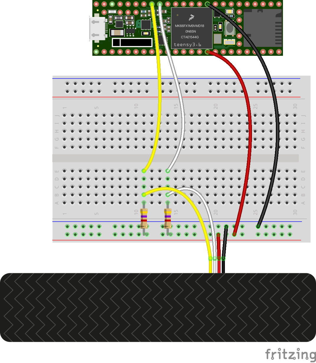
You will note in the above diagram that there are 2 extra resistors added; these are pullup resistors to facilitate I2C communication, required by Teensy LC and 3.0-3.6 (more recent Teensy boards have internal pullups). We recommend using 4.7k. You'll only need one set of pullup resistors for the entire I2C bus, no matter how many sensors you're using.
2. Download and install the Arduino Trill library
Here we assume that you’re using the Arduino IDE to program your Teensy board.
Download the Arduino Trill library from the Trill-Arduino Github repo and install the library using the Arduino IDE. You can find nstructions on installing libraries in the Arduino reference.
3. Open the *-print example for your Trill sensor
After installing the Trill library, browse in the Arduino IDE to Examples->Trill and find the example named after your board followed by -print (such as bar-print or craft-print). Upload it to your Teensy (make sure you have the correct Teensy board selected in Tools > Board in the Arduino IDE), and open the serial monitor. When you touch your Trill sensor you should see the values change.
Teensy notes
-
Teensy 1.0 does not support the Arduino
Wirelibrary. For this reason, the current version of the Trill-Arduino library is not compatible with Teensy 1.0. -
Pullup resistors (4.7k) are required for Teensy LC and 3.0-3.6. Only one set of pullup resistors are required for the SDA and SCL lines, no matter how many sensors you’re using.
Daisy Seed
1. Connect your Trill sensor to Daisy Seed’s I2C bus
The Daisy Seed board has multiple I2C buses. Connect the I2C pins to I2C1, pins 12 (D11 I2C1_SCL) and 13 (D12 I2C1_SDA), and use Daisy’s pin 40 (DGND) and pin 38 (3V3 Digital) for ground and power.
Add pullup resistors from each of SDA and SCL to 3V3, as Daisy Seed doesn’t have on-board pullups.
Like some other boards, pullup resistors are needed to use an I2C device with Daisy Seed. We recommend using 4.7kΩ resistors. You'll only need one set of pullup resistors for the entire I2C bus, no matter how many Trill sensors you're using.
2. Download and install the Arduino Trill library
Here we assume that you’re using the Arduino IDE to program your Daisy board, and you’ve got your environment up and running. (If you haven’t configured your setup yet, see the Daisy guide to getting started with Arduino and make sure you can compile and upload examples to your board.)
Download the Arduino Trill library from the Trill-Arduino Github repo, and install the library using the Arduino IDE. You can find instructions on installing libraries in the Arduino reference.
3. Open the *-print example for your Trill sensor
After installing the Trill library in the Arduino IDE, select File -> Examples -> Trill and find the example named after your Trill sensor followed by -print (such as bar-print or craft-print). Make sure you have the correct board settings selected in the Tools menu. Upload the sketch to your Daisy Seed board. Under Tools > Port make sure you have the USB device selected. Open the serial monitor and ensure it’s at the same baud rate as the sketch (115200).
When you touch your Trill sensor you should see values appear in the serial monitor, and change in response to touch.
Daisy Seed notes
-
Daisy Seed has multiple I2C buses. Use I2C1, which uses pins 11 (SCL) and 12 (SDA).
-
Make sure you have the correct board settings configured in the
Toolsmenu, including thePortfor the serial monitor (use the USB device that’s listed). -
Pullup resistors (4.7kΩ) are required for using Trill with Daisy Seed. Only one set of pullup resistors are required for the SDA and SCL lines, no matter how many Trill sensors you’re using.