Mounting the Trill sensors
Trill sensors are designed to be easily integrated into your projects and can be mounted in various different ways.
This article describes how to physically work with the sensors, how they can be mounted, and what materials you can cover them with.
Table of contents
- Mounting Trill sensors
- 3D printed stands
- Covering Trill with another material
- Cutting sensors to size
- Removing the Grove connector
Mounting Trill sensors
There are various approaches to mounting the Trill sensors in your projects ranging from the simple DIY techniques which can be achieved with hand tools to more sophisticated approaches that use laser cutting or 3D printing. In both cases the important thing to look out for when installing the sensors is the clearance space for the I2C connectors, chip and components.
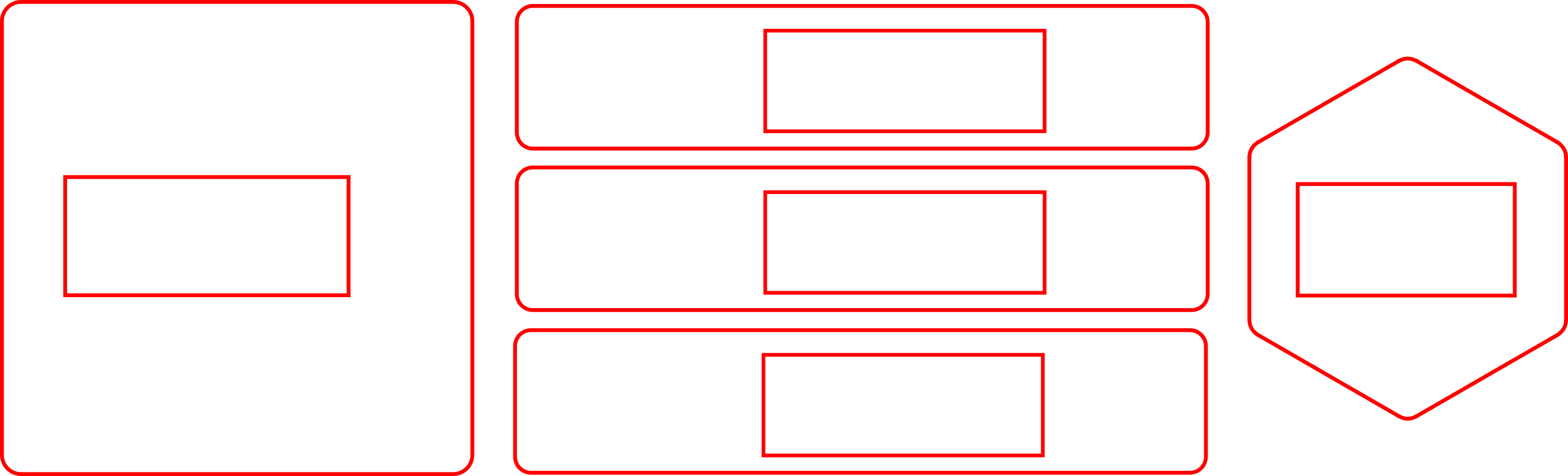
A template for cutting the correct size of holes in relation to the Trill sensor.
On every one of the Trill sensors we have made an effort to make this area as compact as possible and to keep all the components close together. Above you can see template files which illustrate the size of the hole you need to cut when mounting each sensors. This can be achieved by drilling out multiple holes with a hand drill if you are mounting the sensors on wood. These templates can also be used to laser cut a base which is a technique we have often used when creating custom mounts for the Trill sensors.
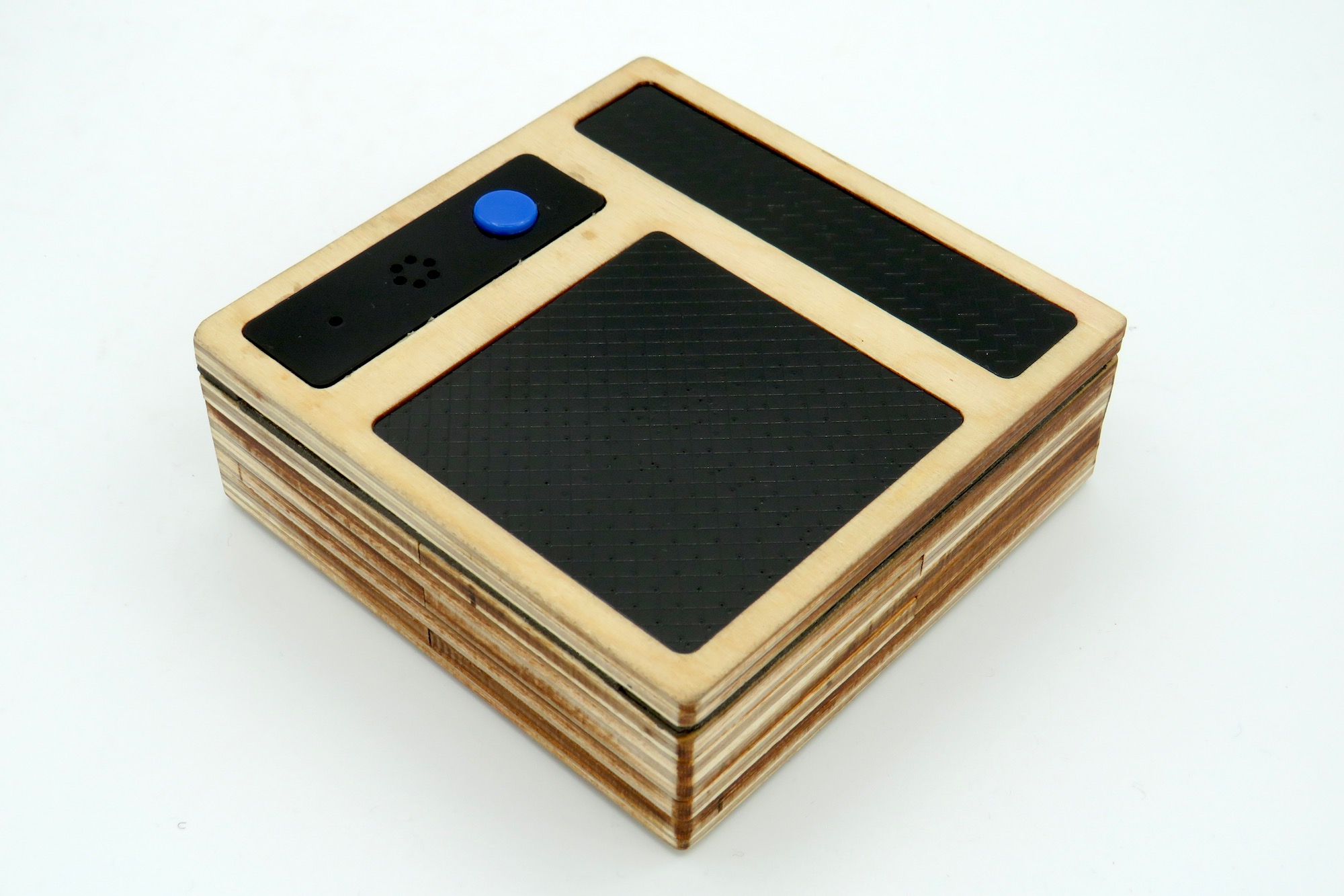
An example of Trill Bar and Trill Square mounted in a layered laser cut box.
The thickness of Trill Bar, Square, Ring and Hex is 1mm so these sensors can be inlayed into a top surface by cutting the outlines into a sheet material of this thickness. Alternatively you can use the raster capability of a laser cutter to etch away a recess of 1mm depth. To attach the sensors we most commonly use a strong and thin double sided tape which has the advantage of being removable if necessary. When trying out tapes it is important to make sure that the tape is non conductive as if it conducts electricity then this will impact the readings you get when it is attached to the back of the sensor.
3D printed stands
We have a set of 3D models of Trill Bar, Square, Ring and Hex as well as some basic mounts which can serve as the basis for your own 3D models and are ready to print at home or at your local maker space. You can find the 3D models here.
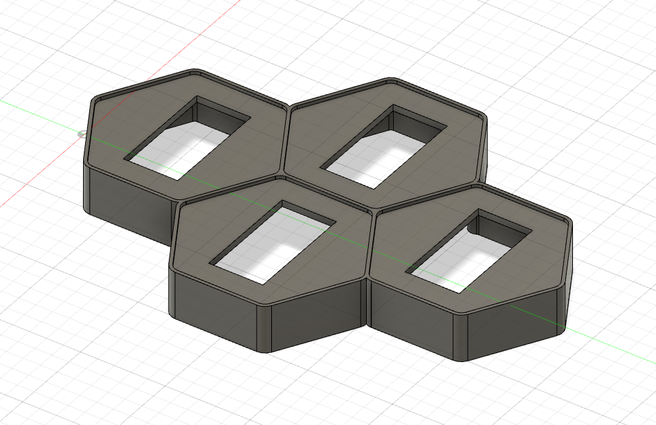
An example 3D enclosure created for multiple Trill Hex sensors tessellated into a keyboard.
Dimensions of all the sensors can also be found on the Trill data sheet.
Covering Trill with another material
Capacitive touch interfaces don’t require direct touch - they can also be triggered by hands in very close proximity as well as direct touches.
This means that Trill sensors can sense touch through a thin layer of non-conductive material, such as tape, paper or vinyl. This can allow Trill sensors to be embedded seamlessly in surfaces, by changing their colour or even hiding them completely.
If covering a custom interface made with Trill Craft, try adjusting the threshold and prescaler settings to get the best responsiveness as described on the settings and calibration page. If you’re using Trill Bar, Square, Hex or Ring, you can set a custom prescaler setting to make the Trill sensors more sensitive so they will be triggered by proximity and not direct touch.
We have experimented with different materials and surface thickness and have found that it is possible to sense through materials of up to around 3mm thick with the correct sensitivity settings. With a prescaler setting of 3 it is possible to detect finger position using a Trill Flex sensor mounted underneath a cutting matt, for example. Bear in mind that the surface also acts like a low pass filter so the overall magnitude and positional accuracy is less than normal with touches being spread across adjacent pads. Depending on your use case this may or may not be important.
We recommend experimenting with different settings by running the general-settings example which allows you to change settings and see the effects all from within the GUI tab of the IDE.
Cutting sensors to size
Trill Bar, Square and Hex can be cut down in size so they fit perfectly into your project.
These sensors all have dashed lines on the reverse to show their minimum footprint. Don't cut inside these lines, or you'll sever crucial connections!
To cut your Trill sensor, first make sure it’s disconnected, then score the back surface (the side with the dotted lines) using a ruler and an Xacto blade. When you’ve determined the perfect size, cut along the scored lines with a strong pair of scissors.
Removing the Grove connector
If space is at a premium and you have an older revision of the Trill sensors with the Grove connector, then you may want to remove the connector on the back of the sensor and solder wires to the pads there instead. See this forum post for a guide on how to do this with images.