Working with Trill Flex
Trill Flex is the sixth addition to the Trill family of touch sensors. Trill Flex ships with a sensor printed on flexible PCB that can conform to virtually any shape, opening up a new world of possibilities for beautiful interaction.
This article describes the details of working with Trill Flex.
Table of contents
Trill Flex for malleable sensing
Trill Flex is the latest addition to our family of capacitive sensors.
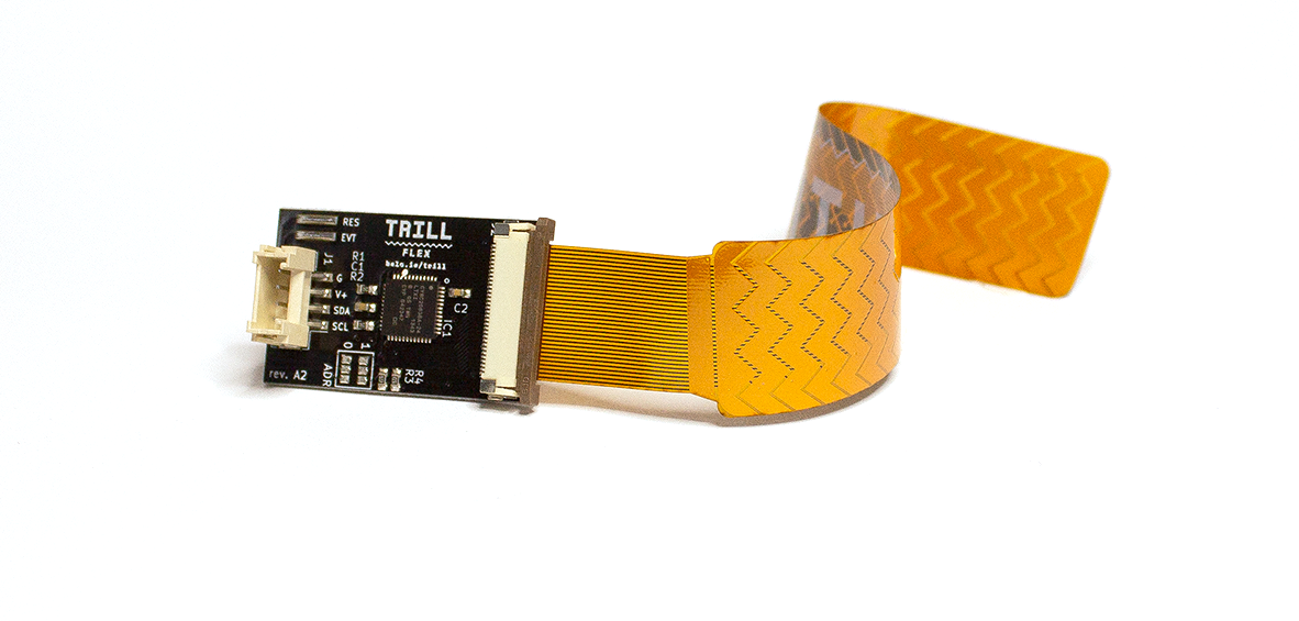
Trill Flex has two parts: a base that holds the capacitive sensing chip, and a sensor printed on flex PCB. Every Trill Flex ships with a one-axis, multi-touch bar sensor, and the flexible PCB means that this sensor can conform to any curve and bend around any corner. This means you can add touch sensing capabilities to everything from existing instruments to entirely new surfaces and applications.
About flex PCB
The vast majority of printed circuit boards (or PCBs) are printed on a rigid fibreglass wafer. This substrate is strong and sturdy, but its rigidity means that it’s often challenging to fit electronics inside tiny or irregular spaces. Flexible PCB has been in use for years in electronics applications, and plays an important role in important products today. Until recently flexible PCB printing was prohibitively expensive for most applications outside of manufacturing, but now that it has become more affordable flexible PCB is finding new purpose other than just a substrate - such as a capacitive touch surface for interactive digital projects!
Working with Trill Flex
Connect the base and sensor
On the end of the base there’s a clip connector. Push the clip up to open it. Insert the end of your flex sensor in the clip, press down firmly, and that’s it - your sensor is ready to go!
Connect Trill Flex to your system
Trill Flex is compatible not only with Bela but with any platform that supports I2C communication.
Trill Flex uses the same 4-wire I2C connection as all other Trill sensors. Just clip in the included QWIIC-to-pin connector, and attach the wires to power, ground, SCL and SDA. (Refer to the Get Started With Trill article if you need to know which wire is which).
Run the flex-visual example
Once you have everything connected you can view the readings from the sensor by running the flex-visual example which will show the you the raw readings from each pad.
If you’re using Bela you can find this in the Examples tab of the Bela IDE. For all other platforms, you’ll find libraries of examples on our Github page.
Designing your own flex sensor
We made the Trill Flex sensor detachable, which means that you can design your own unique flex sensor and swap it right in. This is where the real fun begins - Trill Flex offers 30 channels of capacitive touch sensing to work with. You can make these into a group of 30 buttons of any shape, or combine these channels into a slider that fits your project exactly, or combine them in any way you choose.
We’ve created a step-by-step tutorial on designing a sensor for Trill Flex using KiCad, which takes you through everything from loading the footprint and schematic libraries to drawing your own traces. You can read the article, and it’s also available as a YouTube video.
Though much more affordable than previously, flex PCB printing can still be pricey. To support adventurous makers we've teamed up with our friends at OSH Park, who are offering a $20 discount on flex printing to Trill customers - every Trill Flex sensor ships with a unique discount code.