Pins used by Bela
On this page we list the specific pins used by the various Bela boards and capelets. This page will be a useful resource for people looking to make their own custom designs based on the Bela hardware.
Table of contents
The BeagleBone provides two expander headers: P8 and P9, while the PocketBeagle has (P1 and P2). Details for the functions of all the pins are available in this somewhat hard-to-parse document.
The Bela cape uses pin 24 on header P8 and pins 10-15-17-18-19-20-21-22-23-24-25-26-28-29-30-31 on header P9, plus power and ground.
Additionally, a number of pins are used for the digital I/O: pins 7-8-9-10-11-12-15-16-18-27-28-29-30 on header P8 and pins 12-14-16 on P9. These can be disabled in software if they are needed for other uses.
The Bela multiplexer capelet additionally uses pins 41-42-43-44-45-46 on P8.
The Bela audio expander capelet does not use any additional pins from P8 or P9.
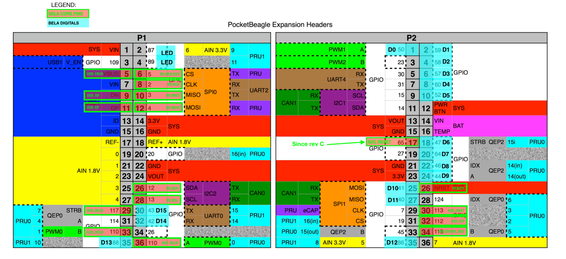
The Bela Mini pocket cape uses pins 5-6-8-9-10-11-12-26-28-29-33-36 on P1 and pins 26-30-32-34 on P2, plus power and ground.
Additionally, a number of pins are used for the digital I/O: pins 1-2-4-6-8-10--18-20-22-24-25-27-35 on header P2 and pins 30-32-35 on P1 and pins P1_02 and P1_04 are used for the on-board LED. These can be disabled in software if they are needed for other uses.
The pin diagram for the I/O and power is available on the on-board IDE and online here.
An up-to-date list of the pins and pinmuxer settings can be found in the Bela device trees and overlays.
Below is a summary of the pins used on Bela:
Bela cape
These are the details for the Bela cape. Where not specified, corresponding pins are used on BelaMini. Refer to the complete pin diagram above for more details.
Audio codec
Uses both McASP channel 0 and I2C bus 2
McASP0
"P9.25", 0x1ac 0x00  /* mcasp0_ahclkx, MODE0 | OUTPUT_PULLDOWN */
"P9.28", 0x19c 0x22  /* mcasp0_axr2, MODE2 | INPUT_PULLDOWN */
"P9.29", 0x194 0x20  /* mcasp0_fsx, MODE0 | OUTPUT_PULLDOWN  */
"P9.30", 0x198 0x20 /* mcasp0_axr0, MODE0 | OUTPUT_PULLDOWN */
"P9.31", 0x190 0x20 /* mcasp0_aclkx, MODE0 | OUTPUT_PULLDOWN */
I2C2
"P9.19", 0x17c 0x73 /* i2c2_scl | P9_19 | MODE3 | INPUT_PULLUP | SLEWCTRL_SLOW */
"P9.20", 0x178 0x73 /* i2c2_sda | P9_20 | MODE3 | INPUT_PULLUP | SLEWCTRL_SLOW */
Analog I/O
McSPI0
"P9.15", 0x040 0x27 /* MODE7 | INPUT | GPIO used for CS of the ADC (Bela only) */
"P9.17", 0x015c 0x27 /* MODE7 | INPUT | GPIO used for CS of the DAC (ADC on Bela Mini) */
"P9.18", 0x158 0x10 /* spi0_d1, MODE0 | OUTPUT_PULLUP */
"P9.21", 0x154 0x30 /* spi0_d0, MODE0 | INPUT_PULLUP */
"P9.22", 0x150 0x30 /* spi0_sclk, MODE0 | INPUT_PULLUP */
Bela button
"P9.27" (Bela) or P2.34 (BelaMini), 0x1a4 0x37 /* gpio3[19] | MODE7 | INPUT | pullup*/
Bela digital I/O
On the BeagleBone (Bela):
"P8.07", 0x90 0x27 /* MODE7 | INPUT | GPIO */
"P8.08", 0x94 0x27 /* MODE7 | INPUT | GPIO */
"P8.09", 0x9c 0x27 /* MODE7 | INPUT | GPIO */
"P8.10", 0x98 0x27 /* MODE7 | INPUT | GPIO */
"P8.11", 0x34 0x27 /* MODE7 | INPUT | GPIO */
"P8.12", 0x30 0x27 /* MODE7 | INPUT | GPIO */
"P9.12", 0x78 0x27 /* MODE7 | INPUT | GPIO */
"P9.14", 0x48 0x27 /* MODE7 | INPUT | GPIO */
"P8.15", 0x3c 0x27 /* MODE7 | INPUT | GPIO */
"P8.16", 0x38 0x27 /* MODE7 | INPUT | GPIO */
"P9.16", 0x4c 0x27 /* MODE7 | INPUT | GPIO */
"P8.18", 0x8c 0x27 /* MODE7 | INPUT | GPIO */
"P8.27", 0xe0 0x27 /* MODE7 | INPUT | GPIO */
"P8.28", 0xe8 0x27 /* MODE7 | INPUT | GPIO */
"P8.29", 0xe4 0x27 /* MODE7 | INPUT | GPIO */
"P8.30", 0xec 0x27 /* MODE7 | INPUT | GPIO */
On the PocketBeagle (BelaMini):
"P2.01", 0x48 0x27 /* MODE7 | INPUT | GPIO1[18] */
"P2.02", 0x6c 0x27 /* MODE7 | INPUT | GPIO1[27] */
"P2.04", 0x68 0x27 /* MODE7 | INPUT | GPIO1[26] */
"P2.06", 0x64 0x27 /* MODE7 | INPUT | GPIO1[25] */
"P2.08", 0x78 0x27 /* MODE7 | INPUT | GPIO1[28] */
"P2.10", 0x50 0x27 /* MODE7 | INPUT | GPIO1[20] */
"P2.18", 0x3c 0x27 /* MODE7 | INPUT | GPIO1[15] */
"P2.20", 0x88 0x27 /* MODE7 | INPUT | GPIO2[0] */
"P2.22", 0x38 0x27 /* MODE7 | INPUT | GPIO1[14] */
"P2.24", 0x30 0x27 /* MODE7 | INPUT | GPIO1[12] */
"P2.25", 0x16c 0x27 /* MODE7 | INPUT | GPIO1[9] */
"P2.27", 0x168 0x27 /* MODE7 | INPUT | GPIO1[8] */
"P2.35", 0xe0 0x27 /* MODE7 | INPUT | GPIO2[22] */
"P1.35", 0xe8 0x27 /* MODE7 | INPUT | GPIO2[24] */
"P1.32", 0x170 0x27 /* MODE7 | INPUT | GPIO1[10] */
"P1.30", 0x174 0x27 /* MODE7 | INPUT | GPIO1[11] */
BelaMini LEDs
"P1.02", 0xe4 0x27 /* MODE7 | INPUT | GPIO2[23], blue LED*/
"P1.04", 0xec 0x27 /* MODE7 | INPUT | GPIO2[25], red LED */
Bela cape Rev C
On Bela cape rev C, also these pins are used:
"P8.32" is the reset pin for the analog I/O ADC and DAC
"P8.33" is the data out line for the DAC.
"P8.34" and "P8.38" are used for the on-board bi-color LED.
BelaMini Rev C
On BelaMini Rev C, the following pin is also used:
"P2.17" is the reset pin for the analog input ADC
I2C1 header (broken out to the molex connector on the Bela cape but unused on the board)
"P9.26", 0x180 0x73 /* i2c1_sda, MODE3 | INPUT_PULLUP | SLEWCTRL_SLOW */
"P9.24", 0x184 0x73 /* i2c1_scl, MODE3 | INPUT_PULLUP | SLEWCTRL_SLOW */
Bela multiplexer capelet
"P8.41", 0x0b0 0x25  /* lcd_data4.pr1_pru1_pru_r30_4, MODE5 | OUTPUT | PRU */
"P8.42", 0x0b4 0x25  /* lcd_data5.pr1_pru1_pru_r30_5, MODE5 | OUTPUT | PRU */
"P8.43", 0x0a8 0x25  /* lcd_data2.pr1_pru1_pru_r30_2, MODE5 | OUTPUT | PRU */
"P8.44", 0x0ac 0x25  /* lcd_data3.pr1_pru1_pru_r30_3, MODE5 | OUTPUT | PRU */
"P8.45", 0x0a0 0x25  /* lcd_data0.pr1_pru1_pru_r30_0, MODE5 | OUTPUT | PRU */
"P8.46", 0x0a4 0x25  /* lcd_data1.pr1_pru1_pru_r30_1, MODE5 | OUTPUT | PRU */