Analog Input
Controlling pitch and loudness
The analog inputs of Bela can read signals that vary continuously in time, as opposed to digital signals that have just two states. In this example we’ll learn about variable resistance sensors and hook up two of them to control the pitch and amplitude of a simple Theremin style instrument.
Table of contents
Analog signals varying continuously in time
Digital signals on Bela only have two states (0 and 1), whereas the value of analog signals can vary anywhere between 0 and 1. Classic examples of an analog sensor are a dimmer switch to control the brightness of a light bulb, or a slider on a mixer to control audio volume.
These type of sensors allow you to have variable control, and set the amount of light or sound to exactly the desired intensity. The digital equivalent of these sensors would be a light switch or a mute button on a mixer where there are only two possibilities (on or off). Bela systems have digital and analog inputs designed for reading different types of signals.
Hardware setup
For this project we’ll connect a force sensing resistor (also know as a FSR, or pressure sensor) to analog input 0 and a potentiometer (also know as a pot or dial) to analog input 1. Both of these sensors work by varying their resistance.
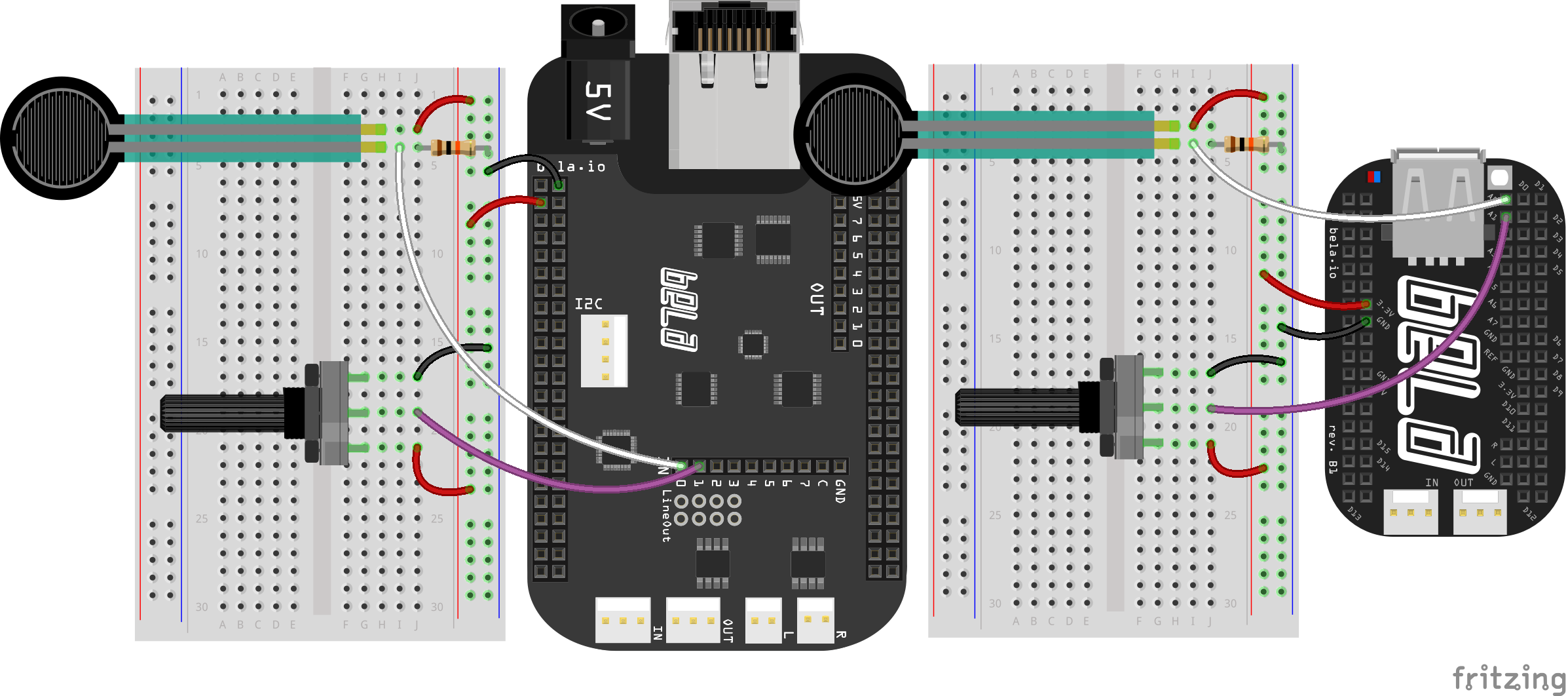
First, note that the potentiometer has three pins, that we can call Ground, Signal and Power. By turning the dial we change the amount of resistance on either side of the central Signal pin of the potentiometer. This changes the voltage that will be present on this middle pin by changing its relative “closeness” to Power or Ground. We can read the voltage on that middle pin with the analog input of a Bela system.
Let’s think about this in a bit more detail. If we have the Ground of our circuit connected to the Ground pin and the 3.3V in our circuit connected to the Power pin then when the dial is turned all the way in one direction, there will be 0V going to the Signal pin, and we read 0. When the shaft is turned all the way in the other direction, there are 3.3V going to the Signal pin and we read 1. In between we read a number that is proportional to the resistance between the pins.
We can imagine the potentiometer as two resistors in series whose relative resistance changes: an one gets bigger the other gets smaller and vice versa. We are reading the voltage at the middle of these two resistors which changes depending on the relative resistance (or impedance) of the two resistors. By moving the dial we change the resistance of both. What we’re seeing in action here relates to a fundamental rule of electronics which we will discuss below.
Voltage divider circuits
When two resistors are connected in series they share the input voltage of the circuit proportionally, depending on the ratio of their individual impedance. If for example we have a 5V source and two resistors that have the same impedance (for example 10kΩ) then each resistor will have an equal share of the voltage (2.5V). The voltage between two resistors can be calculated with the following formula:
Vout = Vin * (R2 / (R1 + R2))
This forms the basis of a voltage divider circuit: By reading the voltage in between two resistors we can tell what the relative ratio is.
The FSR acts in the same way: We’re measuring the difference in voltage share between the static 10k resistor and the variable resistance of the FSR. The 3.3V is shared between the two, which are in series. Pressing the FSR causes the resistance of the sensor to decrease and so we read the voltage going up as the FSR is on the high side of the divider (closer to 3.3V).
The code
Find the analog-input sketch in the Pure Data section of the Examples tab of the Bela IDE.
1. Analog inputs on Bela
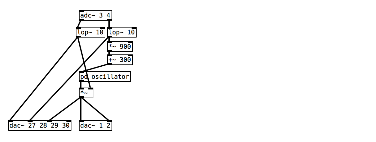
To read from the analog inputs on Bela we use the [adc~] object. In Pure Data this is classically used for audio input. [adc~ 1 2] would give you a stereo audio input to your code. Similarly, on Bela systems [adc~ 1 2] reads from the stereo audio input, but we also use this object to receive input from our analog inputs.
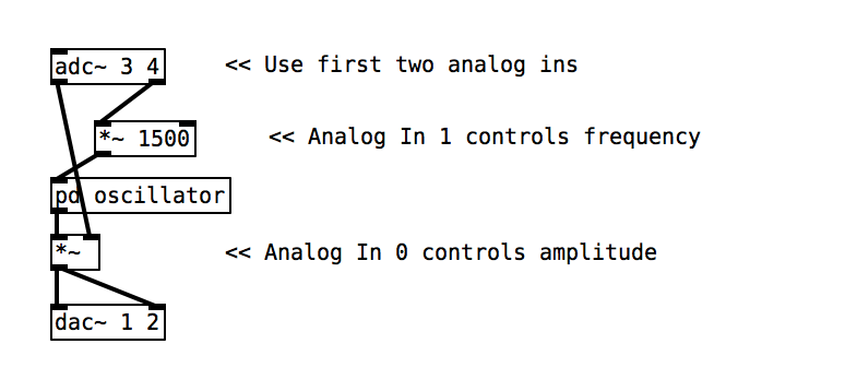
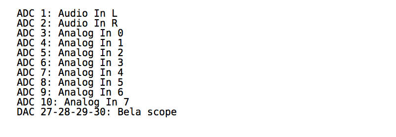
The analog inputs and outputs are sampled at audio sampling rate, so we can handle them in just the same way as you would audio signals. We use channels 3-10 of [adc~] to read from analog inputs 0-7. A table showing the mapping of the analog channels in Bela is below:
2. Mapping
By default the analog inputs come into our Pure Data code between a range of 0-1. To map that range to a more usable range we simply need to multiply using the [*~] object.
As the analog signals are coming in at audio rate we must use the signal rate objects in Pure Data which can be recognised by the ~ at the end of the object name.
3. Sending to the audio output
As we have seen in the previous examples, sending a signal to the stereo audio output of Bela just requires patching the signal to [dac~ 1 2].
Practice tasks
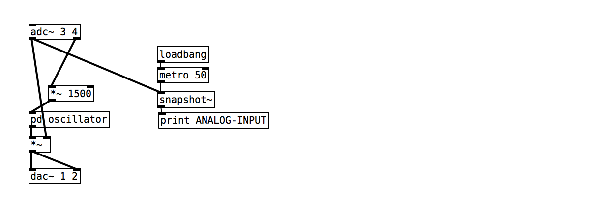
Task 1: Print the analog reading to the console
As the analog readings come into our patch at audio rate, we need to convert them to control rate before we can print them. There is a handy object called [snaphot~] which can do exactly this, by capturing the value of a signal every time it receives a bang message in its inlet. Try banging the snapshot object with a [metro 50], but remember that you need to start off the metro with a [loadbang].
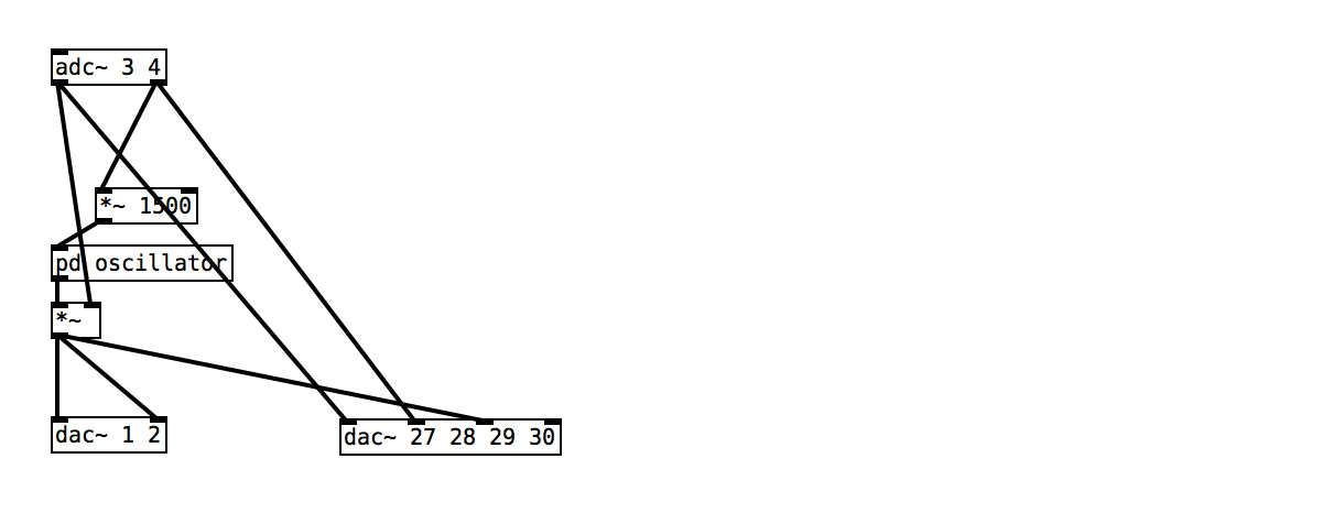
Task 2: Connect the analog inputs and audio to the Bela scope
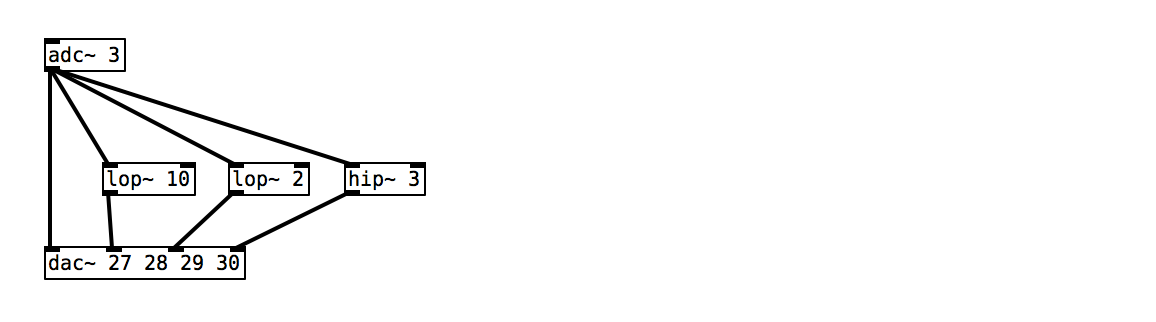
To send signals to the Bela scope use [dac~ 27 28 29 30]. You can send any both the sensor signal and the audio here. Once the program is running you can push the scope button in the IDE to launch the scope in a new tab. For a full description of the scope see [link to be added].
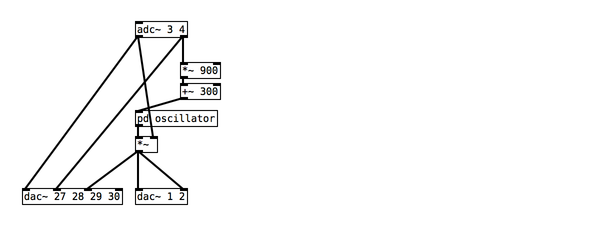
Task 3: Map the frequency range to between 300 and 1200
[+~] and [*~] are your friends.
Task 4: Smooth the signal using [lop~ 10]
As our sensor readings are coming in at signal rate we can apply audio effects and filters to them. The [lop~ 10] object is a low pass filter with a cut-off frequency of 20Hz. This has the effect of smoothing the incoming signal and removing high frequency noise.
Task 5: View the effects of different filter types on the analog input
Connect the smoothed signal to scope alongside the raw signal to see the effect of the filter. Try different cutoff frequencies from 10 to 50 Hz in other scope channels. Lowpass filters allow the lower frequency components of a signal to pass through while attenuating higher frequencies. What this means for sensor signals is that all sudden changes in the signal (which could come from us moving the sensor suddenly, or from some kind of interference in the signal) are smoothed out in favour of the lower frequency changes in the signal. By looking at the signals on the scope you should be able to see these differing effects.