Introduction to the Hardware
Your breadboard and parts
Before going any further with creating Pd patches we’ll introduce the Bela hardware and the signals that we have available. We’ll also explain how a breadboard works so we can start building circuits.
Table of contents
Signals on Bela
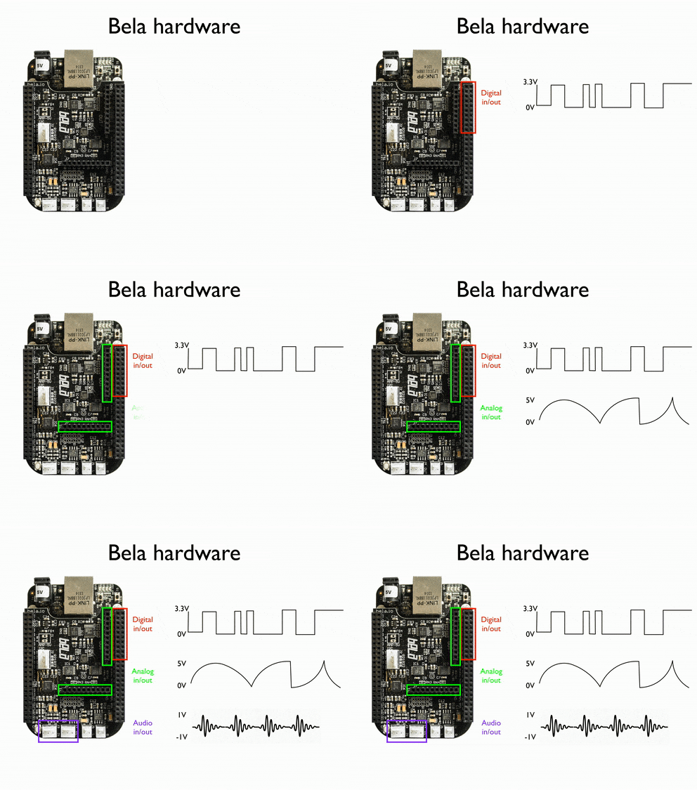
Bela systems handle three different types of signals: digital, analog and audio. An important distinction which we’ll see in many of the examples in this course is that digital signals only have one of two discrete states (on or off), whereas analog signals can vary continuously in time between a minimum and maximum value.

Voltage ranges
Each of the different inputs on Bela boards are suited for different voltage ranges. This is important to note when you are working with different signal types. We will discuss what this means in practice as we go, but for now there is one rule to always bear in mind: The digital I/O on the side headers cannot exceed 3.3V, or you’ll damage your board.
NEVER exceed 3.3V on the digital I/O on the two side headers or you will damage the CPU of the BeagleBone. Always be careful when using 5V supplies!
An introduction to breadboards
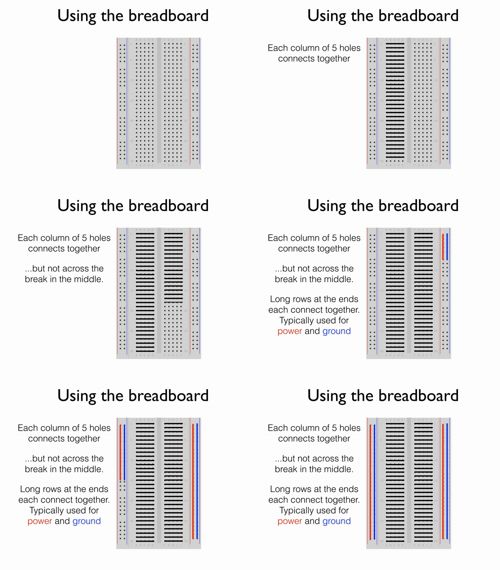
A breadboard is a great way to quickly prototype circuits without having to solder components and cables together permanently. Breadboards consist of rows of copper tracks housed inside the plastic casing. By inserting components into the holes you can connect them together.
Here’s how breadboard holes are connected:

Up next
We are now ready to start building some circuits! First we’ll look at digital output.
