Capacitive Sensing
Turn anything conductive into a sensor
In this tutorial we work with capacitive sensing, which we can use to make any conductive material into a sensor.
Table of contents
Touch sensing with any conductive material
Capacitive sensing has become one of the most widely used types of touch sensing due to its application in mobile phone touch screens. Under the smooth glass of these devices there is a grid of capacitive pads that detect when a finger (or other conductive material) is near the screen.
Let’s take a step back here and explain the principle of capacitive sensing.
Suppose we have a metal plate that we charge up to a known voltage. Charged particles will appear on the surface of the plate, and an electric field will surround it. There’s a certain amount of energy stored in the field, and classically the way we model a system that stores voltage is as a capacitor. The “capacitance” refers to the ratio between charge and voltage.
Now suppose we place our finger near the plate. Even without making physical contact, the finger will alter the electric fields surrounding the plate. This interference changes the charge of the electric field and, ultimately, its capacitance.
By continuously measuring the capacitance of the plate, sensed changes indicate we can get a sense of the proximity of conductive objects. Here we will use Trill Craft, a capacitive sensor breakout board. Trill Craft has 30 channels of capacitive sensing, each one acting like the charged plate that measures change in the electric field. This means that we can have up to 30 conductive objects which can act as touch sensors.
Hardware setup
We are using Trill Craft, a capacitive sensing breakout board that will do the continuous measuring for us. It communicates with Bela via I2C, a communication protocol commonly used for digital sensors. (If you’d like to learn more about I2C, have a look at our I2C primer).
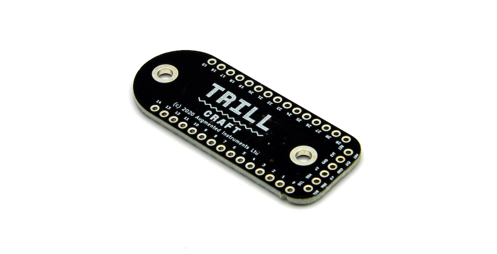
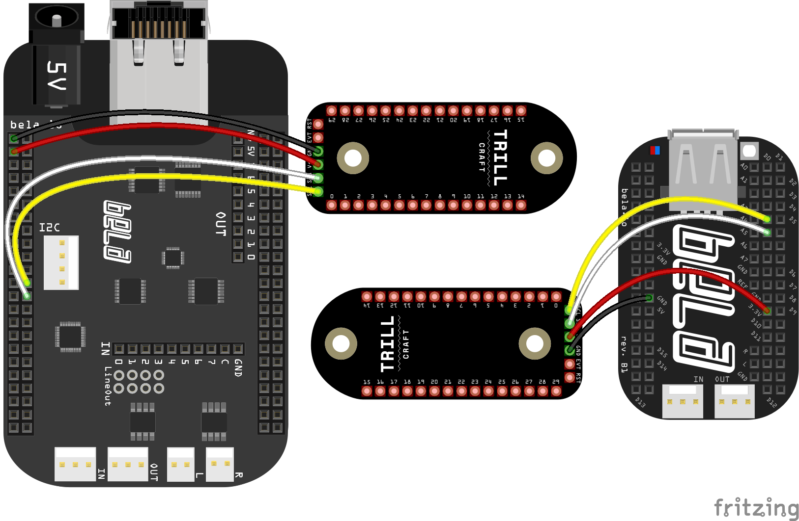
To connect to Trill Craft Bela we need just 4 wires: Power (3.3V), Ground, SDL (Serial Data Line) and SDA (Serial Clock Line). The pins are along the bottom of Trill Craft, and you can connect wires to them directly or solder in a pin header and place it in a breadboard:
The code
Find the capacitive-sensing sketch in the Pure Data section of the Examples tab of the Bela IDE.
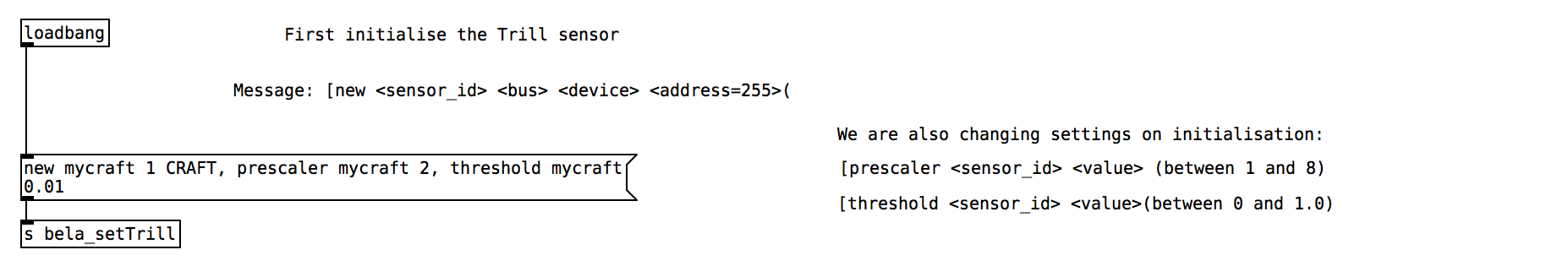
1. Initialising the sensor
The Trill sensor is initialised at the top of the patch, and here we need to specify the sensor type and identifier, as well as some other parameters (such as the threshold above which to read and the prescalar value, which equates to the sensitivity of the sensor). You can use the default values here, but if you’re curious check out our guide to the Trill sensor settings.
2. Reading from the sensor
The Trill Craft readings are received via the [r bela_trill] object, which returns a list of the readings prepended with the sensor_id specified in the initialisation process. So, the first thing to do is to use the route object to check for and remove the sensor_id text and just get the numbers.
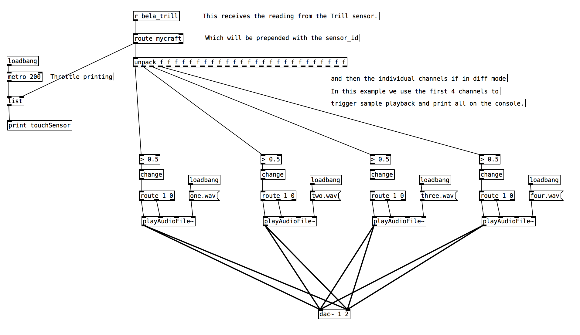
Next we need to split apart the different readings in the list. To do this we use the [unpack] object with the [f] argument to specify that we want floats. You’ll notice that we have this 30 times, once per channel of the sensor. This produces 30 outlets on the [unpack] object.
3. Viewing the readings
This project includes a sketch.js file which is responsible for generating a GUI which will visualise the readings from each channel of the capacitive sensor. Once the project is running you can click the GUI button in the IDE and you will see a bar graph display of the readings from each channel. When changing the prescalar value (which equates to the sensitivity of the sensor) it is useful to use this display to see the effects of different prescalar values.
4. Triggering a sample
We use the [playAudioFile~] abstraction as an easy way to trigger sounds based on the readings from sensor. First we threshold the reading which has a range of 0.0-1.0. We set the value to be 0.5 so when the reading increases past 0.5 we will start playing a sample and when it falls below 0.5 we will stop repeating that sample.
Try touching the pads of channel 1, 2, 3 and 4 on the Trill Craft with your finger. If the threshold value is appropriate you should hear samples being played back.
Practice tasks
Task 1: Connect different conductive materials to the first 4 channels
The behaviour of the sensor can vary quite a bit depending on the materials that are connected to each channel. For some more in depth information on working with Trill Craft and adjusting the settings to be optimal for the materials you have connected check out our
Task 2: Change the threshold value so that each triggers reliably
To change the threshold value adjust the argument in the [> 0.5] object. Check the console to see the range of values which come from each channel.
Task 3: Add extra channels to create a capacitive keyboard
You have 30 channels at your disposal. You can try soldering directly to the pad of Trill Craft and connecting that wire to any conductive material of your choosing.