DIY Pressure Sensor
Making a force sensitive resisitor from scratch
We’ve already worked with force sensitive resistors (FSRs), sensors that change their resistance in response to pressure. In this tutorial we’ll look at making our own homemade versions of that sensor, which are much better value and, most importantly, can be any shape or size!
Table of contents
Creating our own sensors
FSRs are an exciting analog sensor type and can be useful in a number of different situations, particularly when it comes to continuously modulating a parameter or note of a synthesiser. One of the drawbacks of FSRs is that they are quite expensive in comparison to other sensor types and the variety of size and shapes of FSRs is quite limited. We can get around this by making our own FSRs. The material which are going to look at for constructing the sensors was developed by a group of researchers under the direction of Becky Stewart on the embelashed project.
Velostat: Every hardware hacker should have some
Velostat is a black plastic sheet which is pressure-sensitive and conductive. It can be used to detect force on its surface because the conductivity changes when the pressure on the material changes. It is a very flexible material that’s very useful for paper circuitry and e-textiles.
You will need the following materials to build your own FSR:
- A paper template. You can download one to use, or you can go freestyle and create your own.
- A square of Velostat that’s cut to the size of the paper template
- 5mm copper tape. Make sure that the adhesive side is conductive as well!
- Wider copper tape (about 25mm)
- 1k resistor
- Scissors
- Soldering equipment
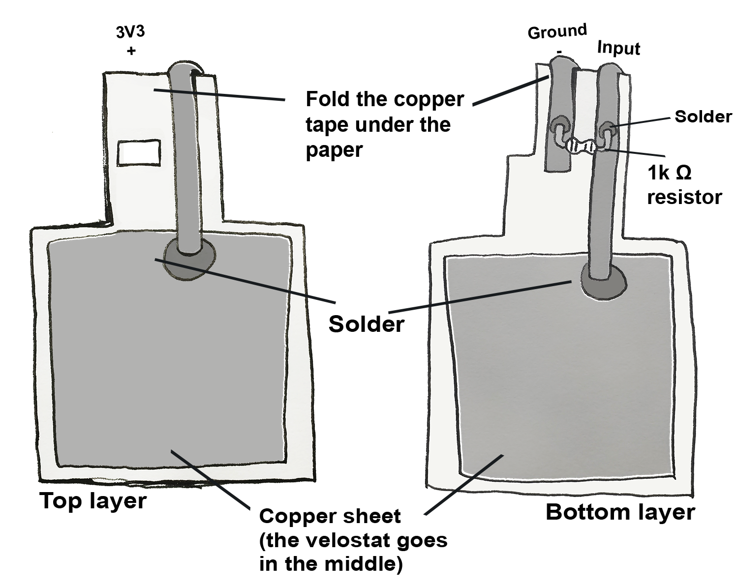
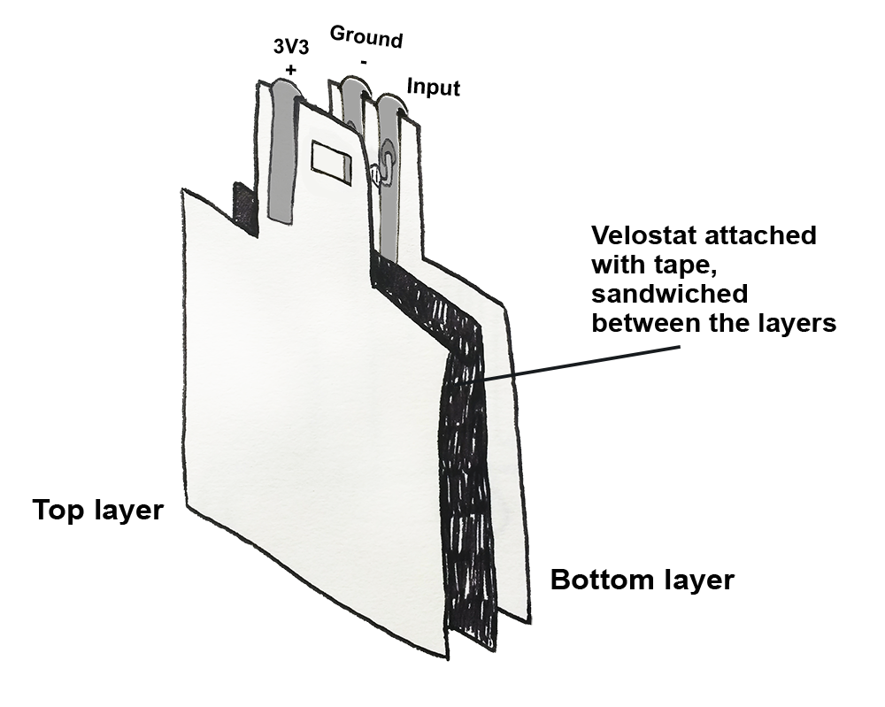
To make an FSR, sandwich the velostat between two squares of copper tape. One square of copper tape is connected to 3.3V. The other square is connected to the 1k resistor that in turn goes to ground. We take our reading from the side with the resistor.
When sandwiching the two sides of your sensor together make sure that 3.3V, your reading and ground do not make contact with each other. You can apply a layer of masking tape as insulation to be sure. If in doubt check the connections with a multimeter.
This circuit is a voltage divider circuit, the other variable resistor sensors we’ve seen such as the FSR and LDR. We have a fixed value resistor (1k), and a resistor which changes in value (the velostat between the pads). We measure the relative change in voltage share between the two.
We need to run three cables from this sensor: One connected to 3.3V, one connected to Ground, and the other one to analog input 0 on the Bela board. Solder these cables in place on the sensor, and plug them in.
If you'd like to know more about creating paper sensors, check out Becky Stewart's excellent Embelashed Toolkit, a resource of tutorials that contains templates, instructions, and even sample Pure Data code.
The code
Find the diy-pressure-sensors sketch in the Pure Data section of the Examples tab of the Bela IDE.
In this tutorial we’re focusing on how to create the sensor, so we’ve kept the patch simple.
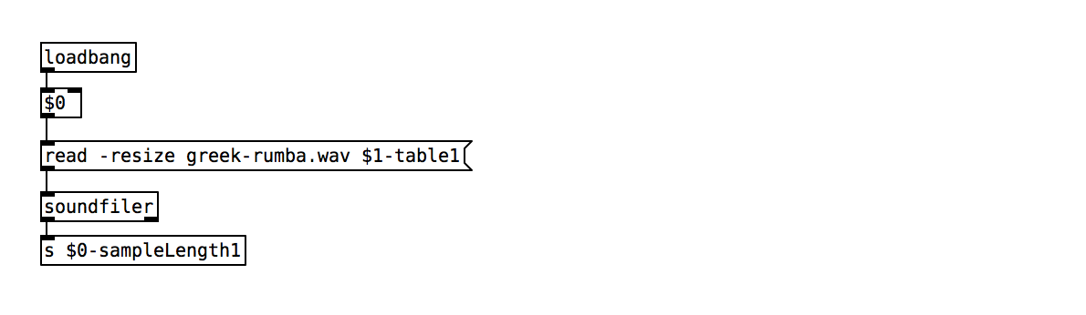
1. Load in the sample
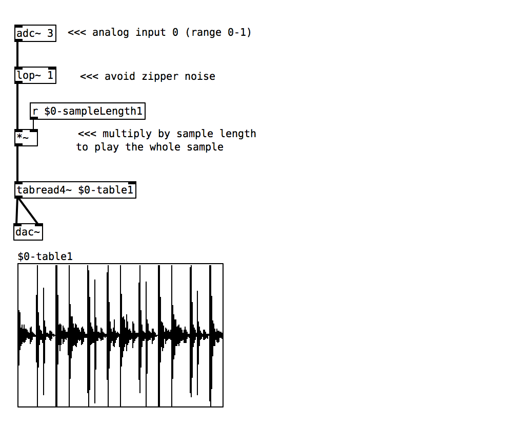
2. Use the sensor to scrub through table
Practice tasks
Task 1: Change the sample
The current sample we are loading in is called greek-rumba.wav. If you would like to change the sample you need to load in another sample via the IDE and make sure to change the sample name in the initialisation phase to the name of your sample.
Task 2: Smooth and remap the sensor signal
You can smooth the signal with [lop~ 20] and remap it with [+~], [*~] and [clip~].
Task 3: Use thresholding to trigger the sample once
In the previous example on working with samples we saw how to trigger the playback of a sample with [threshold~] object. Instead of scrubbing through the table we want to trigger a ramp that goes from 0 to number-of-samples at a set speed.