Digital Input
A one-button drum machine
This example demonstrates how work with the digital inputs of Bela from Pure Data. Here we’ll hook up a button and an LED and then we’ll read from the button to create a simple drum machine.
Table of contents
Reading digital data with two states
In the previous example we used the digital output of Bela to flash an LED on and off. In this example we will look at how we can read signals through the digital inputs.
Both Bela and Bela Mini have 16 digital I/O which can be configured as either inputs or outputs. Digital signals can only be in one of two states - on or off. In the case of Bela the digital inputs can read up to 3.3V when on or 0V when off.
Hardware setup
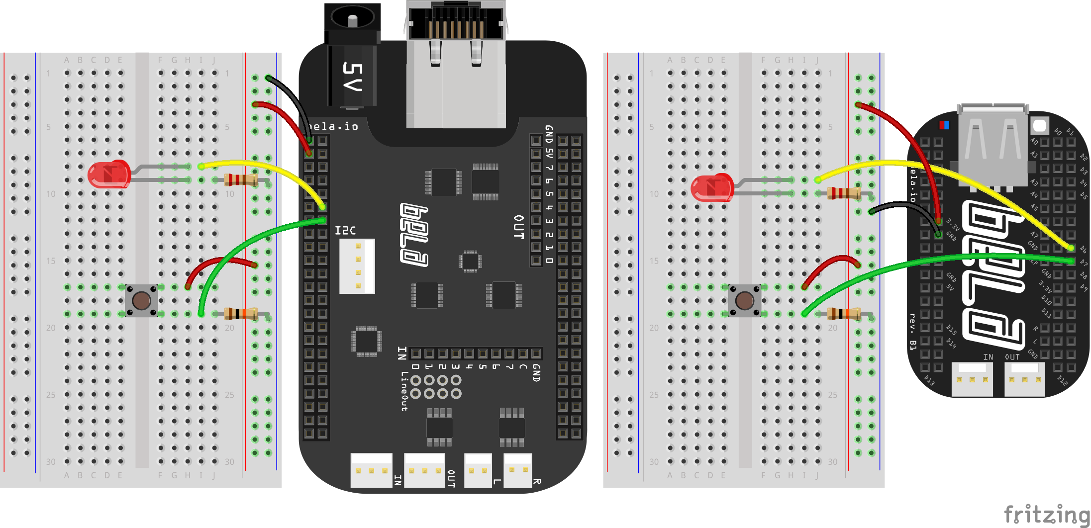
For this project you’ll need a breadboard with a button (with a 10k pull-down resistor), and an LED (with a low-value resistor, such as 240R). See the diagram below for the setup:
Mechanics of a button
Inside the button there are two pieces of metal that are connected to each of the legs of the button. When the button is not pressed, the metal contacts are not touching each other and so the circuit is open. When the button is pressed the two pieces of metal make contact with one another, completing the circuit and allowing electricity to flow. This is what gives us the two states - 0 for unpressed (open), and 1 for pressed (connected). These are the values we read at Bela’s digital input pin.
Make sure the orientation of the button is correct. Instinct would say that the button is connected from one side to the other, but in fact the connection happens between two legs on the same side. The other side is a functional copy of the connections and is there to give the button stability.
Pull-down resistor
You might notice that there’s a 10k resistor included in this circuit, connected to the button. This resistor is responsible for making sure that the reading we get when the button is not pressed is a consistent 0V - without this resistor, that value can fluctuate randomly between the minimum and maximum. This is known as a pull-down resistor, because it literally pulls the reading down towards ground when the circuit isn’t connected.
If we swapped the legs to which the power and ground wires are connected, we would invert the reading (0 when the button is pressed, 1 when nothing is pressed). This is because the resistor would then act as a pull-up, drawing the voltage high when the circuit is open.
The code
Find the digital-input sketch in the Pure Data section of the Examples tab of the Bela IDE.
1. Initialise the digital pin
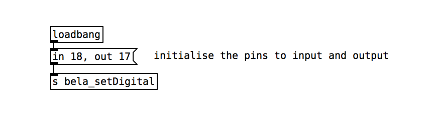
To begin we initialise pin 17 as a digital output and pin 18 as a digital input. Here you’ll see the use of [loadbang] again which is a very useful object that will produce a bang when a project first loads.
2. Read from the button
The [r bela_digitalIn18] receives the value read of the digital input. This object can only have two states (1 or 0) and changes between these states depending on what is read at the pin. When the button is pressed, the circuit is closed, and we will read 3.3V which is represented as 1 on Bela. When the button is open we will read 0V on the input pin which will be represented as 0 on Bela.
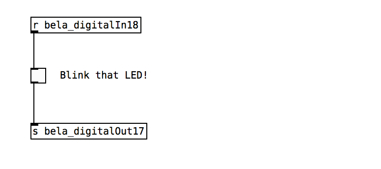
In this example we are mapping the digital input from the button via a toggle to the digital output which controls the LED. The result is simple, now when you push the button you will see the LED lighting up!
Practice tasks
Here’s some exercises to try out, to enhance your understanding of this sketch.
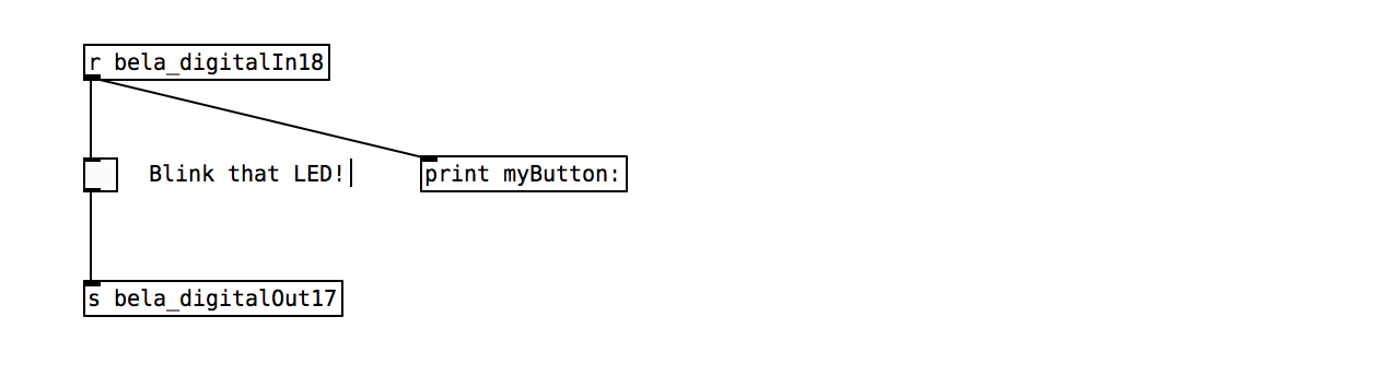
Task 1: Print the value of the button to the console of the IDE
The [print] object will print messages to the Bela IDE every time it receives a message. Note that this has to receive data at control rate, so you cannot connect objects with ~ directly to it. We'll look at how to visualise signal rate data in the next example. You can also add an argument name to be printed next the value.
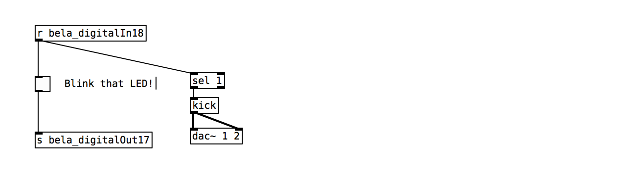
Task 2: Trigger [kick] with each button down
On the right side of this example you'll see the [kick] abstraction, which is expecting a bang in its top left inlet to trigger a simple drum synthesiser. Its output will be an audio signal that needs to be connected to [dac~ 1 2] for anything to be heard.
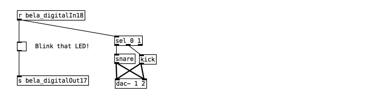
Task 3: Alternate between [kick] on button down and [snare] on button up
Look at the values printed to the console. To select between different integers have a look at the help file of the [select] object.
Task 4: Add a debouncer using [delay]
The metal contacts within mechanical button can bounce off each other before settling into a fixed state. This is sometimes read as multiple quick 0-1-0-1-0-1s. To get rid of this we can use the [delay] object which withholds a *bang* until a certain amount of time has passed. If a subsequent *bang* is received before the set time has passed, the previous *bang* is discarded and the delay starts over. This makes it useable as a debouncer. We need a low value like 3ms but have a look at the effects of larger values too. the [f] stores the actual value (0/1 in our case).

Task 5: Play 4 different frequency tones when pushing the button down
This is an advanced step. Use the [osc~] object to generate a sinetone. We want to count button presses using [f] to store the current value, [+ 1] to increment, [% 4] to wrap around at 4, and [select 0 1 2 3] to generate bangs for each count. From these bangs we can trigger different frequency values used to control the frequency of the oscillator (try banging message boxes with stored values). As a final step try applying an amplitude envelope to the output of the oscillator.
