Amplitude Modulation Synthesis
From tremolo effects to ring modulation
This tutorial section looks at synthesis on Bela in more detail, and we’ll learn to control synthesisers with our connected hardware. In this tutorial, we’ll focus on amplitude modulation (AM) synthesis - a fundamental technique for generating and transforming sound.
Table of contents
The building blocks of modular synthesis
As you might guess from the name of this synthesis technique, amplitude modulation implies varying the amplitude of a signal in time. Direct control over the amplitude of a signal is something we’re all very familiar with – a volume dial on a hi-fi modulates the amplitude (or volume) of the audio signal that’s playing. We saw a similar kind of technique in the analog-input example, where we used the FSR to control the amplitude of the synthesised tone.
Where amplitude modulation really gets exciting is when you use another periodic signal to automate this modulation control, instead of the manual control we have when turning a dial. In this example we’ll create and control a tremolo effect, and then move onto the staple sci-fi effect of ring modulation.
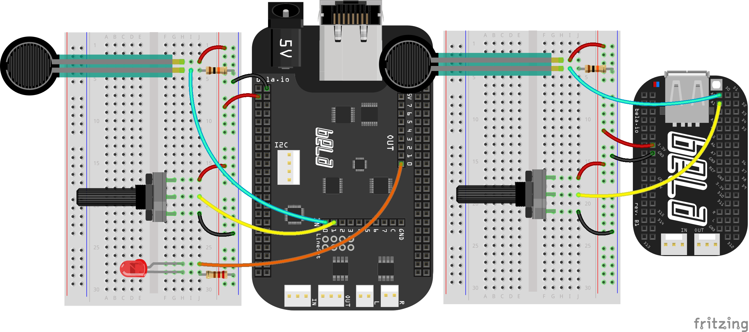
Hardware setup
For this example we have two analog sensors connected to analog inputs 0 and 1 of your Bela system. We’ve chosen an potentiometer and FSR, but you could use two potentiometers if you prefer. An LED is also connected to the first analog output.
The code
Find the am-synthesis sketch in the Pure Data section of the Examples tab of the Bela IDE.
1. Multiplying signals together
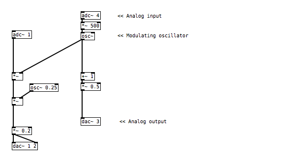
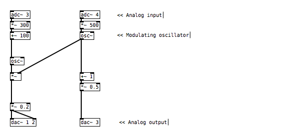
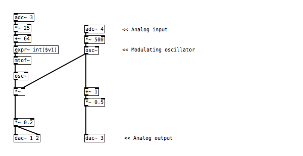
In this example we have a signal generator at the top of the patch that is producing a sine tone. We’re using the first analog input to control the frequency of this tone with a bit of remapping beforehand. To create the amplitude modulation effect, we multiply this signal with another signal which we do with [*~].
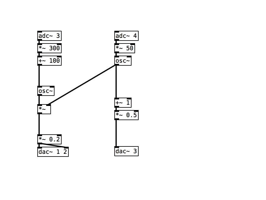
As analog inputs and outputs are sampled at audio sampling rate we can handle them as you would audio signals in your Pure Data code. This is why we have the ~ sign: everything is happening at signal rate.
2. From Tremolo to Ring Modulation
When you listen to this example you’ll hear a wide variety of different effects, depending on the frequency of the modulating signal. For low frequency oscillations you might hear effects that sound like a tremolo, with the signal fading in and out slowly. For higher frequencies the effects get much stranger, and we enter the world of the BBC radiophonic studio and Delia Derbyshire’s infamous sound effects for the Doctor Who series. (Exterminate!)
3. Visualising with the LED
As we have seen in the previous examples, sending a signal to the analog outputs of Bela just requires patching the signal to the relevant inlet of the [dac~] object. In this example we can see that we are sending a signal similar to the modulator to the first analog output of Bela where we have our LED connected. However, we need to do some manipulations to the signal before using to control the brightness of our LED.
The [osc~] object by default gives us a signal which varies from 0 to -1 back to 0 and then to 1 and back to 0 again at a given frequency. If we were to use this to control our LED we would see it flashing twice as fast as the negative part of the signal would be treated as if it were positive. To avoid this we first [+~ 1] to the signal to move it into a range between 0 and 2. We then divide the 2 with [*~ 0.5] which gets us back to the 0 to 1 range that our analog outputs expect.
Practice tasks
Task 1: Remap the range of the modulation effect
As we saw in the previous example, the simplest form of mapping just involves using some basic arithmetic to vary the range of the signal. Consider how we would deal with logarithmic and exponential mappings instead of the linear mappings we have used so far.
Task 2: Add pitch quantisation to the frequency of the top oscillator
There are some very handy objects for converting MIDI notes to the frequency values that we are using to control the pitch of the oscillator (MIDI can be considered like the white and black keys on a piano keyboard). The MIDI to frequency object, or [mtof], is your friend here.
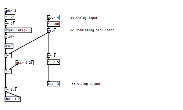
Task 3: Add in a second modulator at a very low frequency
To add a second modulator of the overall amplitude we need to break the signal chain, and add another [*~] object that is in turn modulated by another oscillator. You can try [osc~] or [phasor~] as the modulator (but make sure to set the frequency below 1).
Task 4: Try AM on a real audio stream
Instead of plugging the first oscillator into our Bela system's audio input (the oscillator that currently has amplitude modulation applied), we can use another audio source instead. Connect an audio adapter cable to the audio input on your Bela system, and you can then use a 3.5mm cable to connect your phone. As tempting as it is, don't take your audio signal from the laptop that Bela is connected to as it will result in a ground loop which can create a loud hum! In our code we can add a `[adc~ 1 2]` object at the top, to provide our sketch with stereo audio input.