Analog Output
Fading LEDs for the Knight Rider effect
This tutorial demonstrates how to work with the analog outputs of Bela which can produce a variable voltage. We’ll use the analog signals from the analog outputs of Bela to fade LEDs on and off in phase. (If you are following this tutorial series using a Bela Mini then you’ll have to sit this one out as the Bela Mini does not come with analog outputs.)
Table of contents
What goes up must come down: fading LEDs
In this example, Bela’s eight analog outputs are used to control the brightness of eight differently coloured LEDs (if you don’t have eight LEDs and resistors, just use fewer). Whereas digital signals only have two states (0 and 1), analog signals have continuous variation between 0 and 1. As we discussed in the previous example, classic examples of an analog sensors are a dimmer switch to control the brightness of a light bulb or a slider on a mixer to control the volume of an audio signal.
Hardware setup
For this project we need to connect an LED and a resistor to each of the analog outputs of Bela. Just as in the digital-output example we need a resistor in series with each LED to protect it from receiving too much voltage and burning out.
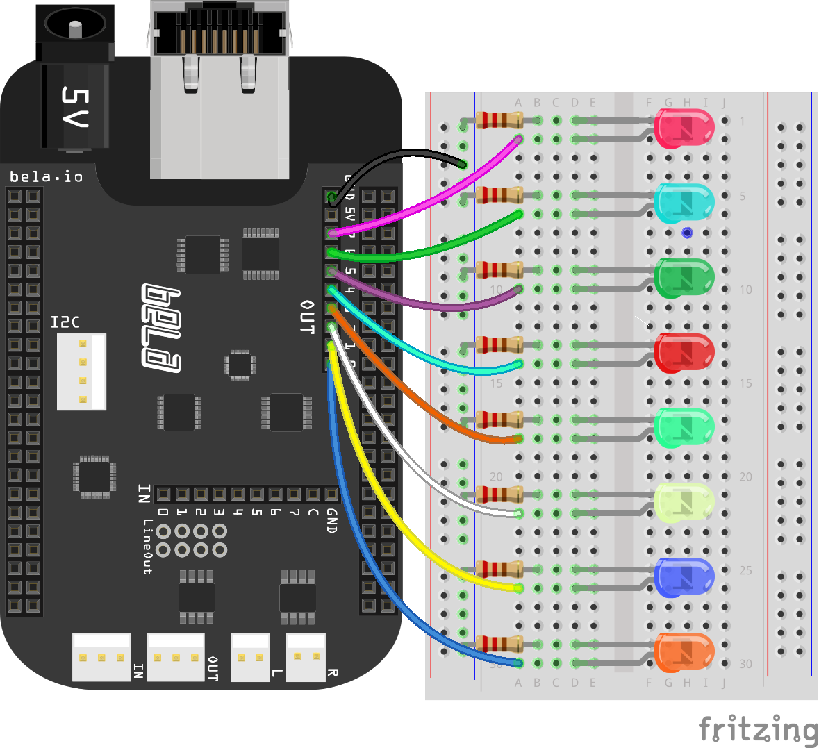
Differently coloured LEDs
You may notice when you get this example up and running that the differently coloured LEDs have different brightnesses. This is because the optimum operating voltage of LEDs is different for each colour (if you’re interested you can find the optimum forward voltage of an LED on its datasheet). In the example we’re using 220Ω resistors, but f you wanted to ensure a uniform brightness across all colours then you would have to select a more exact resistor value for each colour.
The code
Find the analog-output sketch in the Pure Data section of the Examples tab of the Bela IDE.
1. Analog outputs on Bela
Analog outputs function in a very similar manner to what we saw in the previous example. To send a signal to the analog outputs of Bela we use the [dac~] object. In Pure Data this is classically used for audio output, and [dac~ 1 2] would give you a stereo audio output. In this case we will use channels 3-10 of [dac~] to send out the analog signal, which corresponds to analog outputs. Here’s a table showing the mapping of Pure Data’s audio channels to Bela’s analog outputs:
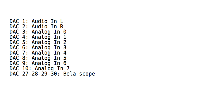
The analog inputs and outputs are sampled at audio sampling rate, so we can handle them as we would audio signals in Pure Data code. This is why we have the ~ sign: everything is happening at signal rate.
2. Ramp generators
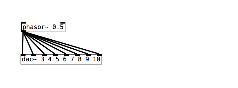
This simple patch will send a sawtooth wave generated from [phasor~] to the analog outputs of Bela. The frequency of the sawtooth wave will be 0.5Hz, and this wave shape is characterised by a gradual increase from 0 to 1 and then a sudden drop back down to 0 (similar to the teeth of a saw if seen on an oscilloscope).
3. Sending signals to the analog output
As we have seen in the previous examples, sending a signal to the analog outputs of Bela just requires patching the signal to the relevant inlet of [dac~ 3 4 5 6 7 8 9 10]. In this example the same signal is being sent to all the 8 analog outputs of Bela.
Practice tasks
Task 1: Make the LED fade at a different rate from each other
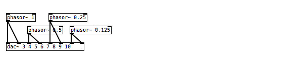
We currently have one signal generator which is the [phasor~] object. This sends the same signal to all eight analog outputs. In order to have each LED fade in at a different rate we will need to have multiple signal generators which are running at different frequencies. Remember that the argument given to the [phasor~] object defines its frequency.
Task 2: Create a ‘chaser’ which goes from the 1st to the last LED
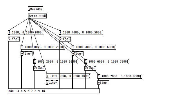
[vline~] is useful here - this object allows you to define a linear ramp from one value to another with precise timings. It requires a bang to start the ramp generation, so include a [metro] object to produce a bang periodically. Check the help file of [vline~] to see how you can define the timing structure of the ramps you will use to control the LEDs. Consider how you will delay the start of the different [vline~] objects.
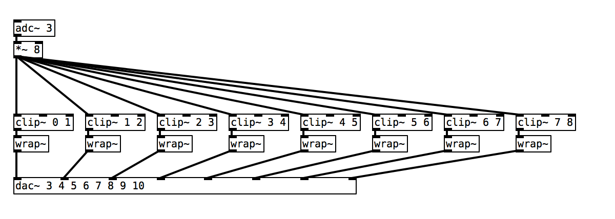
Task 3: Use a potentiometer to fade between each of the active LEDs
To begin, connect a potentiometer to the first analog input (see the previous example for a diagram). We can then remap the output from this potentiometer from 0.0 - 1.0 to 0.0 to 8.0 by using the [*~] object. The next step is to divide the signal into eight different sections that can be used to control the brightness of the individual LEDs. Have a look at the [clip~] and [wrap~] objects.