Distance sensor
Using Distance Sensors with Bela
To finish this section on sensors we will look at how we can sense distance using ultrasound.
Table of contents
Sensing distance with ultrasound
Distance sensors can allow you to detect how far away an object is by sending out an ultrasonic signal and measuring the time it takes for that signal to return. The particular sensor that we’ll focus on in this example is the HC-SR04 Ultrasonic Ranging Module which can detect objects between 2cm to 400cm depending on the settings.
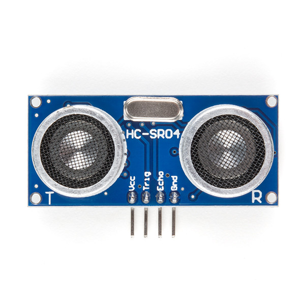
The sensor consists of two main parts, the transmitter and receiver (marked T and R) and the circuitry necessary to operate them. The principle of operation is very similar to sonar and to how bats navigate space without sight. Every few milliseconds a high frequency series of pulses are sent from the transmitter. The receiver then checks for any reflections of the original signal. Through a simple calculation involving the speed of sound it is possible to understand how far away the reflecting object is.
Hardware setup
The HC-SR04 distance sensor has 4 pins in total. VCC should be connected to 5V and GND to a ground pin. The TRIG pin is used to tell the sensor to produce the pulse and so will be connected to a digital out (digital 11). ECHO is where we’ll receive the output from the receiver and so should be connected to a digital input (digital 12) but via a voltage divider to lower the overall voltage. This require two resistors connected as shown below: 1K and 2.2K Ohms.
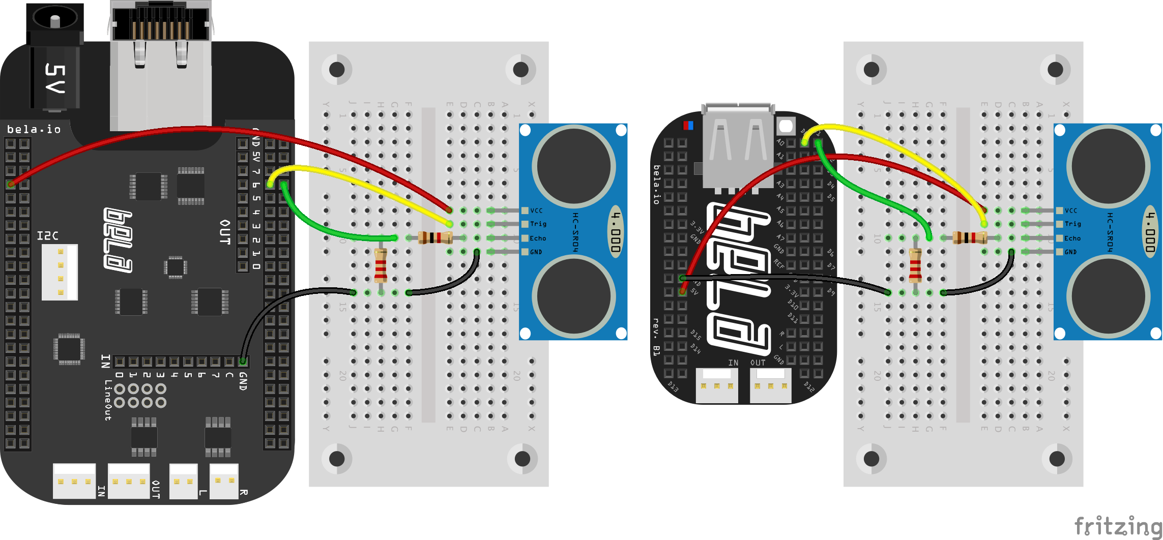
In this example we are using 5V as that is the required voltage for the sensor. We are also connecting to the digital pins on the Bela board. It is important that you are extremely careful to not connect the 5V directly to any of the digital pins as there is the risk that you will permanently damage your board. The voltage divider with the two resistors is essential for lowering the voltage to a safe level for the digital pins.
The code
Find the ultrasonic-distance-sensor sketch in the Pure Data section of the Examples tab of the Bela IDE.
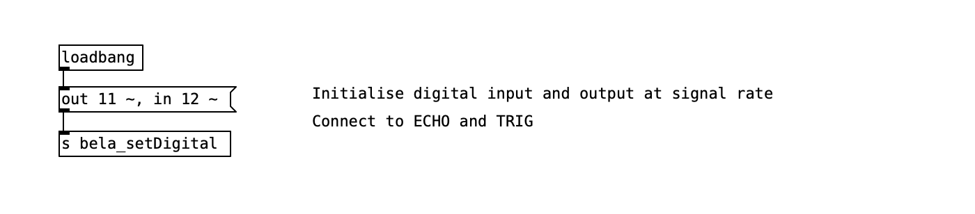
Initialising the digital pins
We want to initialise both the digital pins at audio rate with the ~ symbol. This means that instead of reading or writing to these pins once per block (every 16 samples in the default case of Pure Data) we can instead read and write from the digital pins on every sample. This is necessary for this example as we need to send receive messages on the digital pins at high speed.
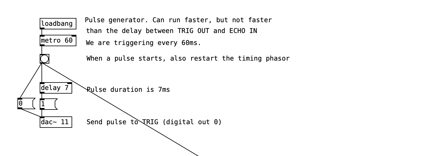
Triggering the ultrasonic emitter
The emitter will send out a sequence of high frequency pulses when a momentary voltage is received on the TRIG pin of the sensor. In this example we are sending a 7ms pulse every 60ms. This triggers the emission of the sequence of pulses.
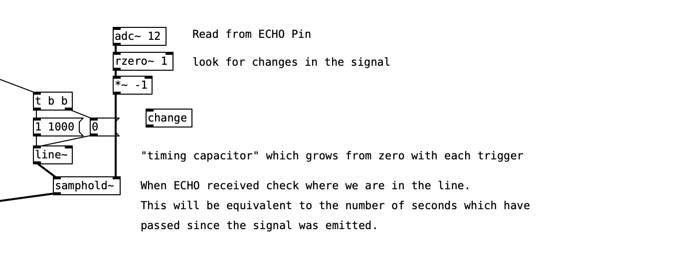
Receiving the echo
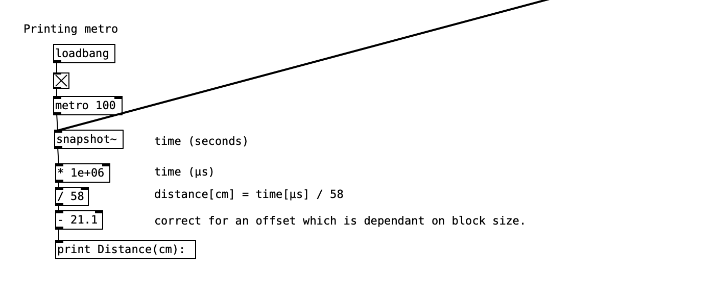
We then need to read from the receiver the reflections of the ultrasonic signal. When the sequence is received at the ECHO pin we will read a high signal. By calculating the time difference between the triggering and the echo we can simply calculate the distance between the sensor and an object which reflects back the ultrasonic waves. We can use the following equation: time[us] / 58 = distance[cm].
Calculating and printing
The final step is to print the distance value after the calculation which includes a correction for an offset which is dependent on the block size of the project.
An alternative method
To get a smoother and more accurate reading from the sensor try running the custom-render-distance-sensor example which reads from the sensor with a bit of c++ code that runs in the background of the PD patch. The Pure Data example in this case is very simple and just receives the reading from the sensor. To learn more about combining Pure Data patches and custom c++ code have a look at the advanced example custom-render.
Practice tasks
Task 1: Theremini!
As a first exercise let's try and change the frequency of a sinetone in a manner similar to a theremin. Map the distance reading directly to the frequency of an oscillator. You might want to multiply the range up so that you get a wider variety of pitches and apply some smoothing to recreate a more authentic theremin sound.
Task 2: Divide the range into 3 states
Figure out the maximum and minimum values by looking at what is printed to the console and then use [threshold~] to define different areas in the range where you want different things to happen. Try for example to change between 3 different set pitches of the base oscillator.
Task 3: Trigger different samples based on distance
The [playAudioFile~] abstraction used in the previous example will make sample playback quite easy. Once a threshold is passed try to trigger the playback of a sample once.