Frequency Modulation Synthesis
The birth of digital synthesis
In this tutorial we examine Frequency Modulation (FM) synthesis, a technique which can achieve varied timbres with relatively limited resources, and enabled a whole new generation of digital synthesisers in the 1980s.
Table of contents
FM Synthesis
In the previous AM synthesis example we modulated the amplitude of a signal continuously in time. With FM synthesis, we instead modulate the frequency of our signal continuously in time.
FM synthesis was first invented by John Chowning at Stanford university in late the 1970s when he was looking for a way to re-synthesise complex sounds with limited computing resources. He discovered that with this relatively simple technique, which is also computationally efficient, it is possible to recreate complex timbres like those you would expect from acoustic instruments. The Yamaha DX series of digital synthesisers realised the true capabilities of FM synthesis, and these went on to define the sound of the 80s era of pop music. In the DX synthesisers (the DX7 being the most famous of these), FM synthesis is used to to recreate a whole variety of instrument-like tones.
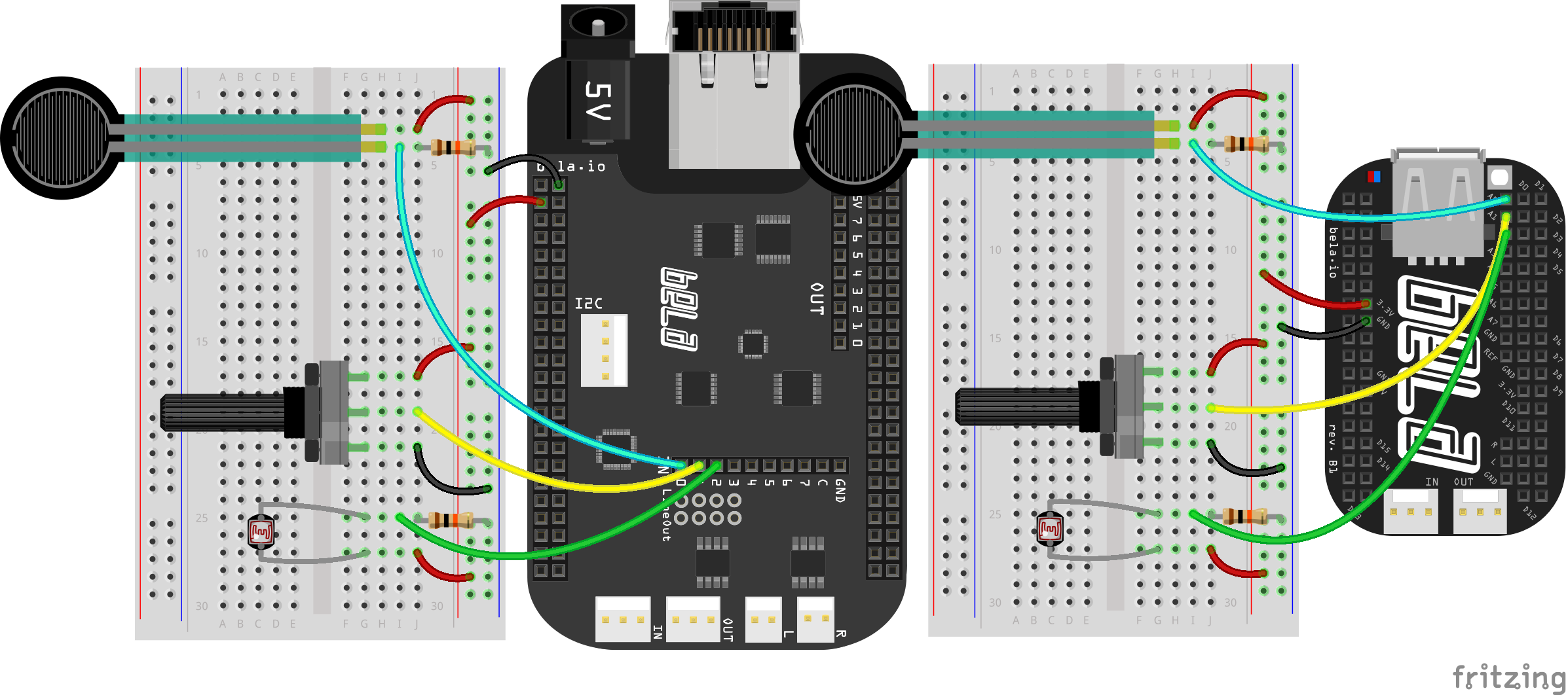
Hardware setup
For this example we will hook up 3 analog sensors to the first three analog inputs. We recommend a potentiometer, FSR and LDR (light dependent resistor). The LDR requires a similar circuit to the FSR because it works in a very similar way. As it receives light the resistance of this sensor drops, and we read a higher voltage on the analog input pin of Bela. This is similar to the behaviour of the FSR which, when squeezed, drops its resistance.
The code
Find the fm-synthesis sketch in the Pure Data section of the Examples tab of the Bela IDE.
1. Carrier and Modulator
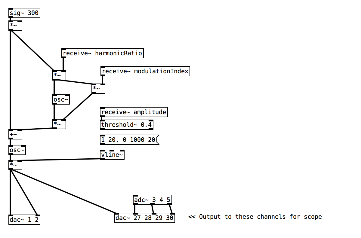
FM or Frequency Modulation Synthesis is based on the use of at least two oscillators; a Carrier and a Modulator. In the code below, the first analog input [adc~ 3] is mapped to the carrier amplitude, while the other two inputs are mapped into the modulator frequency and amplitude (commonly known as the harmonic ratio and modulation index respectively).
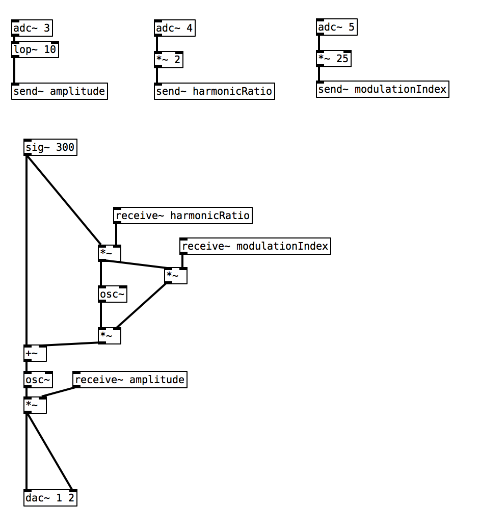
The Carrier Frequency is most related to the pitch or the fundamental frequency and is usually controllable with a keyboard or other MIDI input. In this example the frequency of the carrier is fixed by default and set to 300Hz via [sig~ 300].
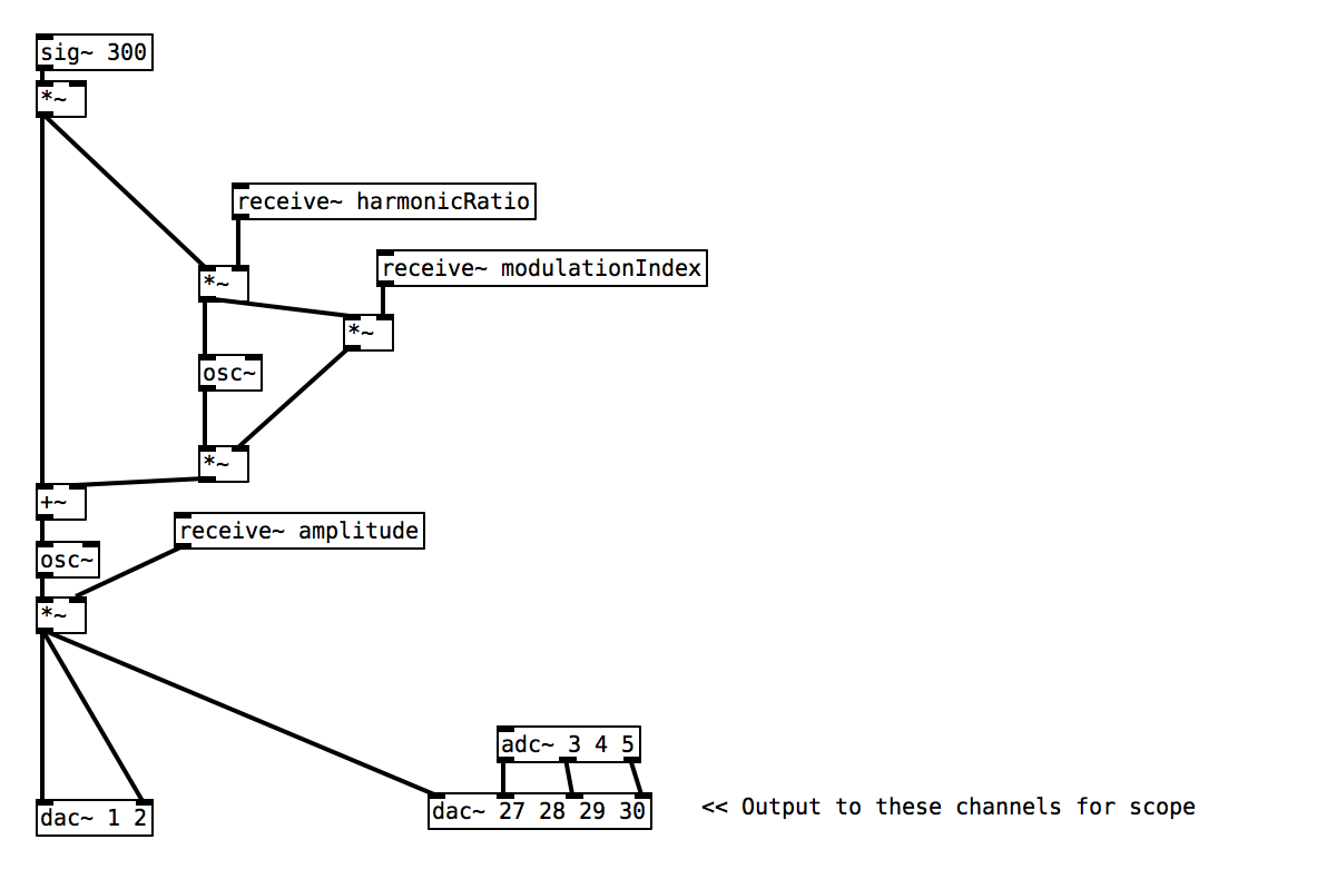
The modulating oscillator is used to alter the frequency of the carrier oscillator (hence FM).
By looking at the above code we can see that if the modulation index is set to 0.0 then there will be no modulation effect on the carrier oscillator as when we get to the [+~] which sums the modulation oscillator together with the carrier frequency we will be adding 0.0.
2. Sends and Receives
The [send~] and [receive~] objects allow you to pipe signals around in a patch without having to draw the physical connections between objects – just make sure they have the same name. You’ll notice in this example that our analog input signals come into the patch at the top, and these signals are then manipulated with [*~] or [lop~] before being connected to a [send~] object, which has an additional argument of a name. An object with the same name receives this signal - no patch cords required.
Practice tasks
Task 1: Map the LDR to an appropriate range using the scope
The LDR is connected to [adc~ 5] and is multiplied by 25 before being sent to control the modulation index. Try covering the sensor with a fingertip to see the effect of a higher resistance, and shining a torch into it to see the effect of a low resistance (a phone torch works well).
Due to the nature of the LDR you might notice that you are not getting a full range from the sensor. This is because the range of readings are dependent on the ambient light levels in room, and the brightness of the torch. Connect the LDR to the scope [dac~ 27] and measure the minimum and maximum readings you are getting. With these two numbers you will be able to remap the signal using simple arithmetic ([-~] and [*~]) so that it gives the full range 0.0 - 1.0.
Task 2: Use the FSR to trigger an envelope once over a threshold
[threshold~] will let you know when a signal goes over a certain limit. [vline~], as we have in the analog-output example, will generate an envelope that can be used to control the amplitude of the synthesiser. (You can find more information in the Pure Data help patches on how the objects work.)
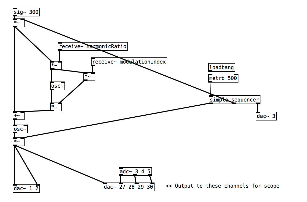
Task 3: Use [simple-sequencer] to generate a pattern of notes
We have created an abstraction for you which can be used to create a simple arpeggiated pattern of notes. If you double click on the [simple-sequencer] object in Pure Data you will learn about the kind of signals it is expecting to receive in its inlets alongside the type of signals which it will generate from its outlets.